Centrifuge rotor

a centrifuge rotor and centrifuge technology, applied in centrifuges and other directions, can solve the problems of unattainable essential increase of the maximum rotational speed and the weight of these rotors, and achieve the effect of relieved rotor body from strain and high strength

Active Publication Date: 2013-01-24
EPPENDORF SE
View PDF7 Cites 5 Cited by
  • Summary
  • Abstract
  • Description
  • Claims
  • Application Information

AI Technical Summary

Benefits of technology

[0020]Further, a contour ring for a positive connection with a centrifuge lid is advantageously arranged at the rotor body, wherein the contour ring is configured as a separate element having a higher strength than the porous...

Problems solved by technology

Although such centrifuge rotors made of fiber composites have lower weight compared with the rotors made of metal, ...

Method used


Image

  • Centrifuge rotor
  • Centrifuge rotor
  • Centrifuge rotor

Examples


Embodiment Construction

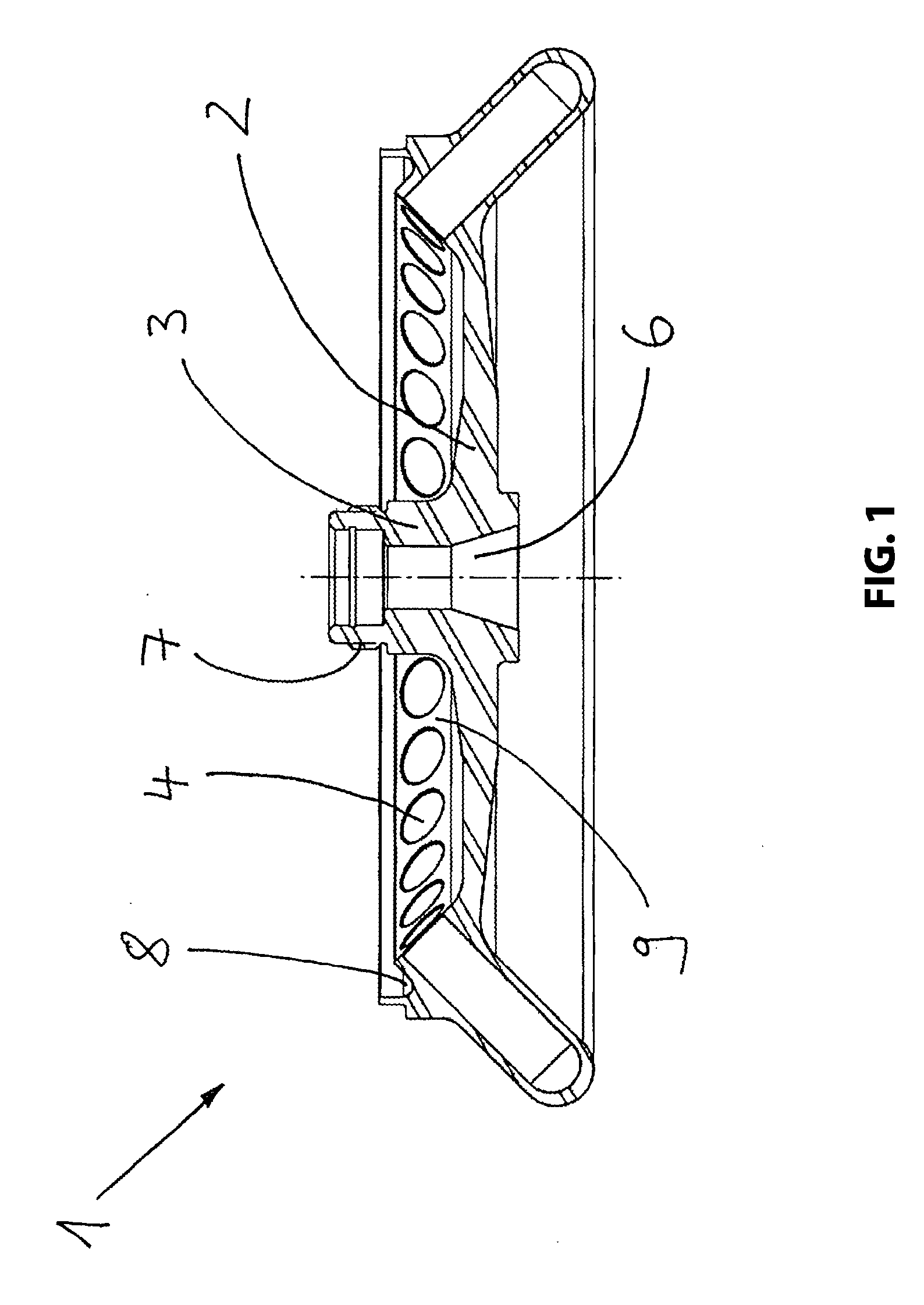
[0027]FIG. 1 illustrates a known centrifuge rotor 1 including a rotor body 2 made of a solid metal, usually aluminum. Around a rotational axis the rotor body 2 includes a hub portion 3, and in radially outer portions receiving sections 4 for samples to be centrifuged are provided. The hub portion 3 includes tapped holes (not shown) for identifying the centrifuge rotor. Further, a receiving section 6 for arranging the centrifuge rotor 1 at the drive unit of a centrifuge is provided in the hub portion 3, and above the receiving sections 4 the hub portion 3 includes a thread 7 for non-positive connection of the centrifuge rotor 1 with a centrifuge lid not shown. This centrifuge lid can engage a recess 8 in a form locking and friction locking manner to seal the centrifuge space 9 in an aerosol-tight manner.

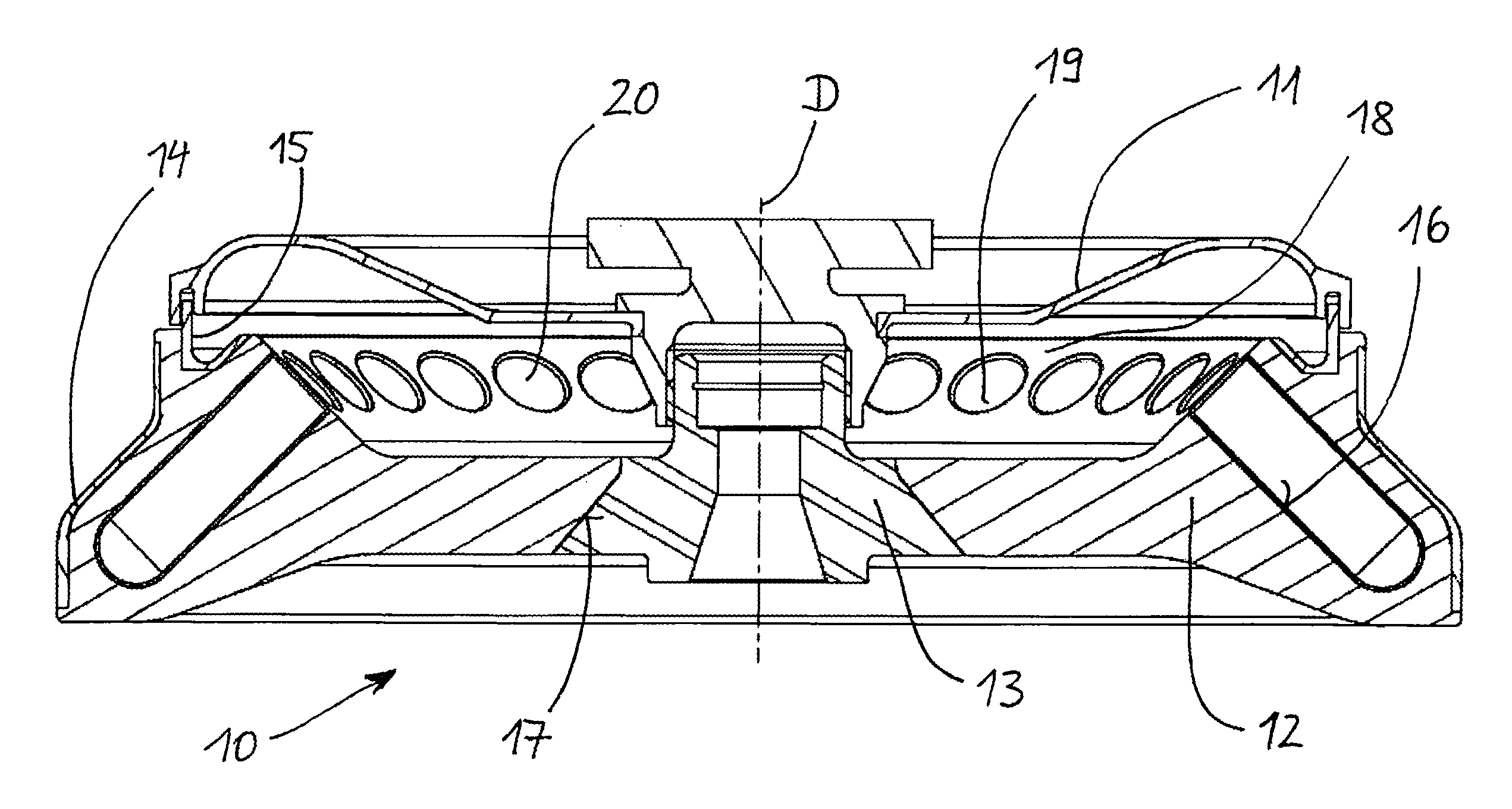
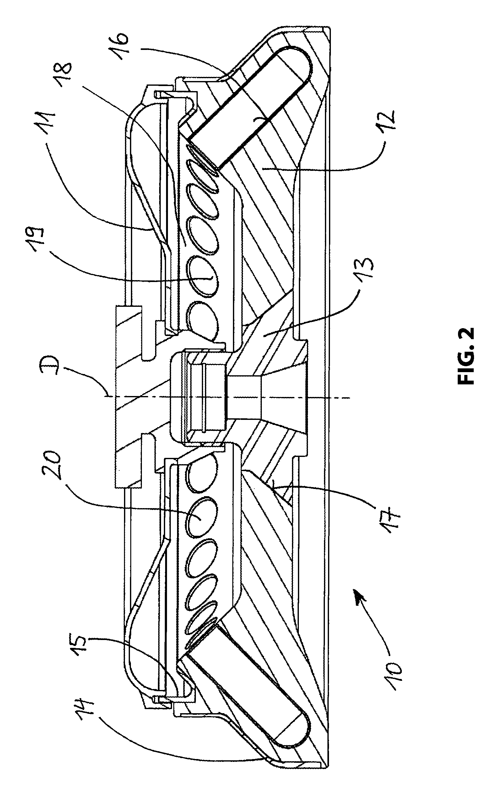
[0028]FIGS. 2 to 4 schematically illustrate the centrifuge rotor 10 according to a first advantageous embodiment of the present invention, wherein FIG. 2 is a sectional view schematic...


PUM


Abstract

The present invention relates to a centrifuge rotor, in particular a laboratory centrifuge rotor, including a rotor body, wherein the rotor body at least partially includes a porous metal or a porous metal alloy and an armoring located radially outside with respect to the rotation axis of said rotor body is provided. The centrifuge rotor allows centrifugation to be performed in a shorter time than previously and at a higher rotational speed. This results, inter alia, in higher RCA (relative centrifugal acceleration) values and thus in a very rapid separation of the constituents of the substances to be centrifuged.

Description

RELATED APPLICATIONS[0001]This application claims priority from and incorporates by reference U.S. Provisional Patent Application 61 / 572,167 filed on Jul. 12, 2011.FIELD OF THE INVENTION[0002]The present invention relates to centrifuge rotors, in particular for laboratory and industrial centrifuges according to the preamble of claim 1.BACKGROUND OF THE INVENTION[0003]Such centrifuges are used for separating the constituents in heterogeneous systems, wherein the effectiveness and efficiency of the centrifugation essentially depends on the rotational speed of the centrifuge rotors. Therefore, an increase of the rotational speed of such centrifuges is constantly aspired. However, an increase of the rotational speed entails an increased load acting on the centrifuge rotors for which reason centrifuge rotors are normally made of high-strength materials, such as steel, titanium and aluminum, but the use of fiber composites is also known from DE 102 33 536 A1, for example.[0004]Although su...

Claims


Application Information

Patent Timeline
IPC IPC(8): B04B7/08
CPCB04B7/085B04B5/0414
Inventor SCHMIDT, MATTHIASARNOLD, STEFFENSCHULZE, FRITZ PETERBITTNER, RAJKOBOENISCH, STEFAN
Owner EPPENDORF SE
Why Eureka
Try Eureka