Controller for use with gas turbine engine

a gas turbine engine and control valve technology, applied in combustion control, combustion types, combustion using catalytic materials, etc., can solve the problem of less than the initial difference in temperature difference between inlet and outlet temperatures, and achieve the effect of increasing the open ratio of bypass control valves, reducing the amount of main fuel, and increasing the concentration of carbon monoxid

Inactive Publication Date: 2013-01-31
KAWASAKI HEAVY IND LTD
View PDF5 Cites 15 Cited by
  • Summary
  • Abstract
  • Description
  • Claims
  • Application Information

AI Technical Summary

Benefits of technology

[0009]Preferably, the controller comprises means for increasing the open ratio of the bypass control valve to maintain the outlet temperature of the catalytic combustion unit within a predetermined rage when the main fuel to be supplied to the catalytic combustion unit is decreased in response to a load decrease. When the load decreases, the amount of main fuel is decreased. This may result in a deterioration of combustion in the burn-out zone. For example, the outlet temperature decreases due to a drastic reduction in catalytic reaction rate and therefore the concentration of carbon monoxide increases. According to the invention, the open ratio of the bypass control valve is increased and, as a result, an amount of air bypassing the catalytic combustion unit is increased. This causes a decrease in the air-fuel ratio of the gas being supplied to the burn-out zone from the catalytic combustion unit, which stabilizes the combustion state in the burn-out zone.
[0010]Preferably, the controller comprises means for decreasing the open ratio of the bypass control valve to maintain the outlet temperature of the catalytic combustion unit within a predetermined rage when the main fuel to be supplied to the catalytic combustion unit is increased in response to a load increase. When the load increases, the amount of main fuel is increase. This may result in the temperature in the catalytic combustion unit increases excessively beyond a heatproof temperature of the catalyst. According to the invention, the pre-burner fuel control is operated to decrease the inlet temperature and the open ratio of the bypass control valve is decreased to decrease the amount of air bypassing the catalytic combustion unit, which increases the air-fuel ratio in the catalytic combustion unit to cause a fuel lean condition in the catalytic combustion unit. This prevents the catalyst from being damaged by burning.
[0011]According to the controller for gas turbine engine, the aged-deterioration is determined. Specifically, the inlet temperature varies with the deterioration of the catalyst so that a difference between the inlet and outlet temperatures differs from that measured when the catalyst is new or not deteriorated. Then, a change of the difference corresponds to the deterioration of the catalyst. Therefore, the exhaust gas maintains an initial quality regardless of the deterioration of the catalyst by controlling the amount of fuel to the pre-burner and thereby controlling the inlet temperature so as to compensate the deterioration of the catalyst.

Problems solved by technology

According to this arrangement, the deterioration of the catalyst decreases the outlet temperature, which results in that the temperature difference between the inlet and outlet temperatures becomes less than the initial difference.

Method used


Image

  • Controller for use with gas turbine engine
  • Controller for use with gas turbine engine
  • Controller for use with gas turbine engine

Examples


Embodiment Construction

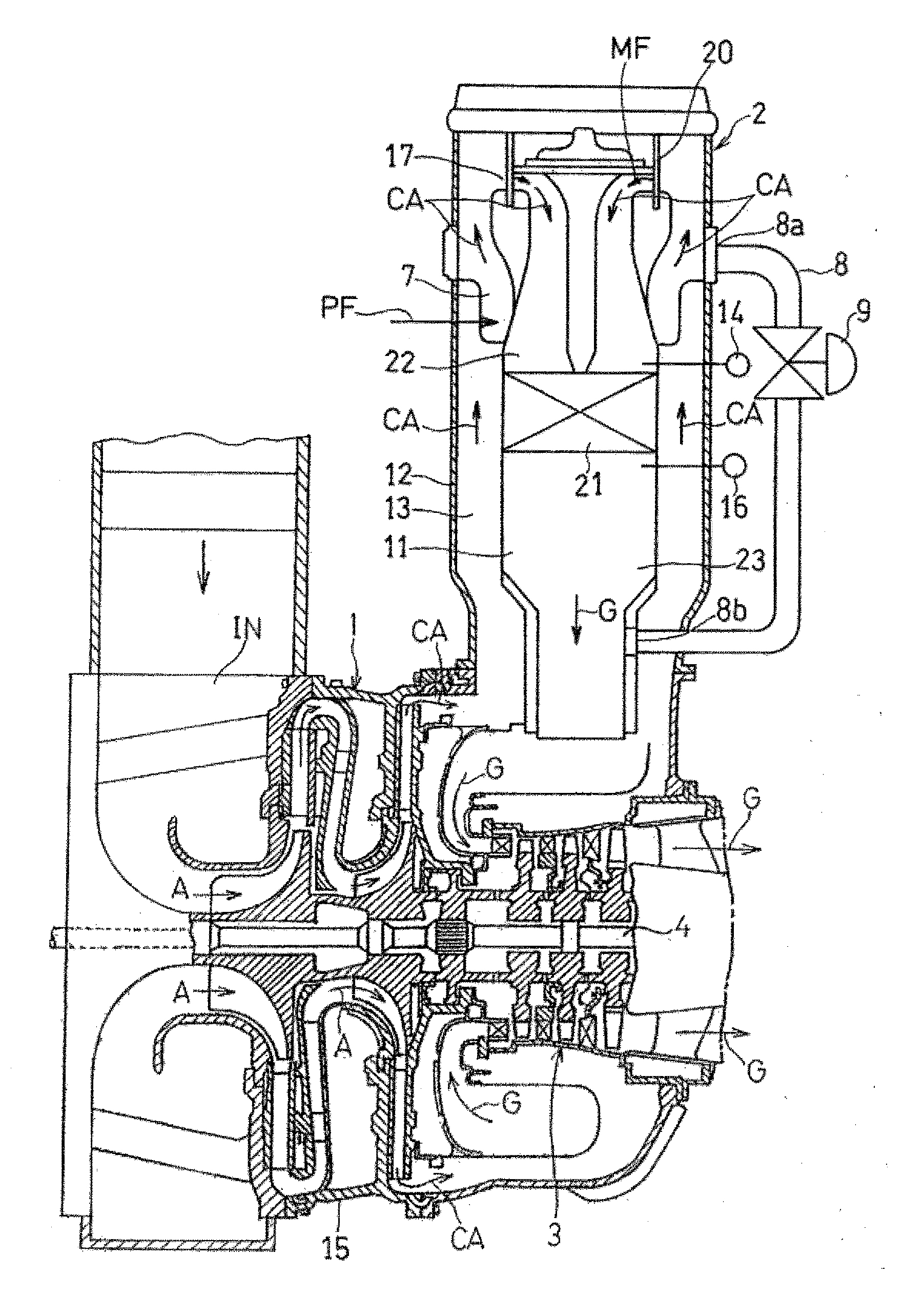
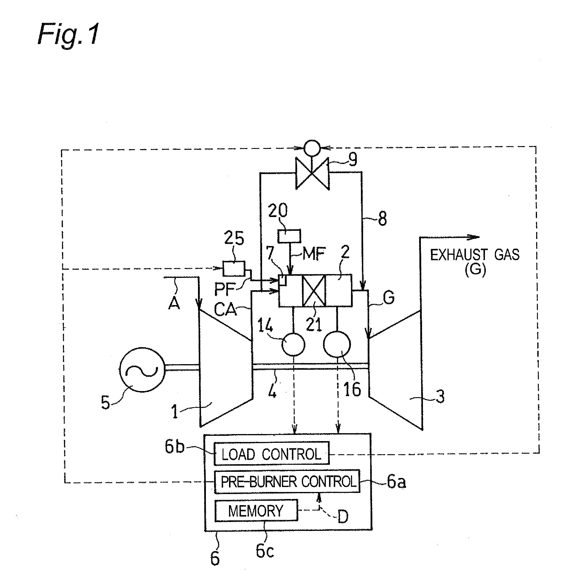
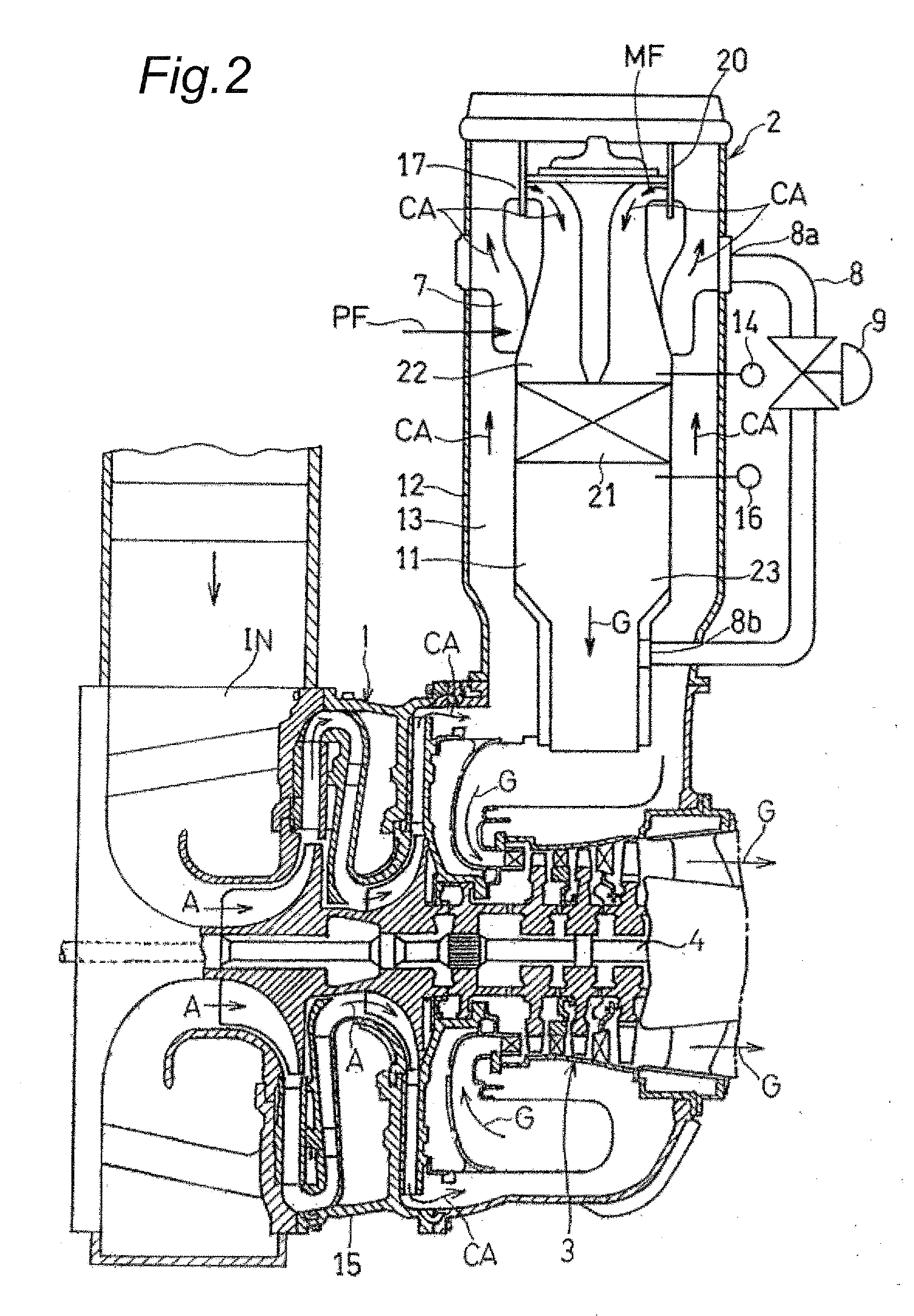
[0018]With reference to the accompanying drawings, a preferred embodiment according to the invention will be described below. FIG. 1 is a block diagram showing a general structure of a catalytic gas turbine engine which incorporates an engine controller according to the first embodiment of the invention. The gas turbine engine comprises a compressor 1 for drawing and compressing air A, a combustor 2 with a catalytic combustion unit 21 for mixing the compressed air CA from the compressor 1 with fuel and combusting the mixture in the catalytic combustion unit 21 and a turbine 3 which is rotated by the use of the combustion gas G generated by the combustor 2. The turbine 3 is connected to the compressor 1 and a rotational load or electric generator 5 through a rotating shaft 4 so that the rotation of the turbine 3 is transmitted to the compressor and the electric generator 5 for the driving of the compressor 1 and the electric generator 5. The combustion gas G is then transported throu...


PUM


Abstract

Provided is a controller for use with a gas turbine engine, which ensures a stable combustion regardless of the deterioration of the catalyst and elevated characteristics of the exhaust gas. The controller 6 is used in the engine which comprises a combustor 2 for combusting a mixture of compressed air from a compressor 1 and a fuel under the existence of catalyst, the combustor having a catalytic combustion unit 21 bearing the catalyst and a pre-burner 7 provided on an upstream side of the catalytic combustion unit with respect to a flow of the compressed air for supplying and combusting a pre-heating fuel PF with the compressed air CA. The controller comprises a memory 6c for memorizing an initial temperature difference D between inlet and outlet temperatures t1, t2 measured at inlet and outlet of the catalytic combustion unit with non-deteriorated catalyst accommodated therein, and a pre-burner control for calculating a present temperature difference between the inlet and outlet temperatures measured in an operation of the gas turbine engine and controlling an amount of the fuel to be supplied to the pre-burner according to a deterioration Δd of the catalyst which is provided by a difference between the initial and present temperature differences D and d.

Description

TECHNICAL FIELD[0001]The present invention relates to a controller for use with a gas turbine engine incorporating a catalytic combustor which combusts a mixture of compressed air generated by a compressor and fuel such as natural gas under the existence of catalyst to generate high-temperature combustion gas.BACKGROUND OF THE INVENTION[0002]There has been known a catalytic gas turbine engine which comprises pre-combustion and pre-mixing sections provided on the upstream side of the catalytic combustion unit and a burn-out section provided on the downstream side of the catalytic combustion unit. In this gas turbine engine, the catalytic combustion becomes unable to generate sufficiently high temperature combustion gas due to the age-related deterioration of the catalyst. This results in that a high-temperature zone in the burn-out section at a temperature of about 1,300° C. reduces and then the combustion becomes unstable. The unstable combustion may increase carbon monoxide concent...

Claims


Application Information

Patent Timeline
Patent Type & Authority Applications(United States)
IPC IPC(8): F02C9/00
CPCF02C3/205F02C9/28F23C13/02F23N1/042F23R3/40F23N2023/54F23N2037/12F23N2037/20F23N2041/20F23N5/022F23N2223/54F23N2237/12F23N2237/20F23N2241/20
Inventor KUROSAKA, SOASHIKAGA, MITSUGUOGATA, MASAHIROHOSOKAWA, YASUFUMINISHI, MUNEYUKISATO, TSUYOSHI
Owner KAWASAKI HEAVY IND LTD
Why Eureka
Try Eureka