Appliance airflow detection using differential heating of electronic devices

a technology of electronic devices and differential heating, applied in the field of applications, to achieve the effect of dissipating 99 the power

Active Publication Date: 2013-01-31
HAIER US APPLIANCE SOLUTIONS INC
View PDF6 Cites 11 Cited by
  • Summary
  • Abstract
  • Description
  • Claims
  • Application Information

AI Technical Summary

Benefits of technology

[0008]In another aspect of the disclosure, an appliance comprises a heat source, a chassis and a cooling air passageway for circulating air around at least a part of the chassis is disclosed. An air flow measuring device that is supported and immersed within the cooling air passageway measures a rate of airflow through the cooling air passageway and includes a first device (e.g., a first thermistor or like device) that generates a self-heating effect and a second device (e.g., a second thermistor or like device) that does not self-heat and thus measures the local ambient temperature around both devices. The first device and the second device provide a voltage differential that corresponds to a difference in temperature between the first device and the second device that is inversely proportional to the rate of airflow. The two devices may be substantially identical (i.e., the same part number) but, they do not need to be if their differences are properly considered in the circuit design. The first device and second device are operated in such a manner that the first device experiences significantly more power dissipation than the second device, therefore, the first device self-heats significantly more than the second device. This can be accomplished by Pulse Width Modulating (PWM'ing) the two devices at different duty cycles. For instance, the first device can be operated at 99% while the second device can be operated at 1% (i.e. the same PWM control signal can be used to drive both circuits, with one circuit using an inverted representation of the control signal), thus the first device would dissipate 99× the power of the second device. Alternatively, the first device could be operated continuously (100%) while the second device is activated infrequently (e.g., at 1 ms once every second). In an analog implementation the difference in temperature-dependent voltages or difference in temperatures generated by the two devices is compared against a reference voltage to determine if the airflow rate is above / below a predetermined threshold. This implementation uses an analog means to determine the differences, where the analog means includes at least one of an operational amplifier, instrumentation amplifier, or comparator. In a digital (microprocessor) implementation the two device voltages would be converted to a temperature indication by a variety of means (calculation, look-up table, etc.), and the difference in temperature would be calculated and compared against a predetermined threshold. A digital means may be used to measure the differences in temperature-dependent voltages or differences in temperature, which includes a microprocessor with analog / digital ports to sample the two voltages and calculating the voltage differences mathematically

Problems solved by technology

In the first phase the first device is activated in such a manner to produce self-heating; a relatively large amount of current is forced to flow through the first device, however, the second device does not experience this current.

Method used


Image

  • Appliance airflow detection using differential heating of electronic devices
  • Appliance airflow detection using differential heating of electronic devices
  • Appliance airflow detection using differential heating of electronic devices

Examples


Embodiment Construction

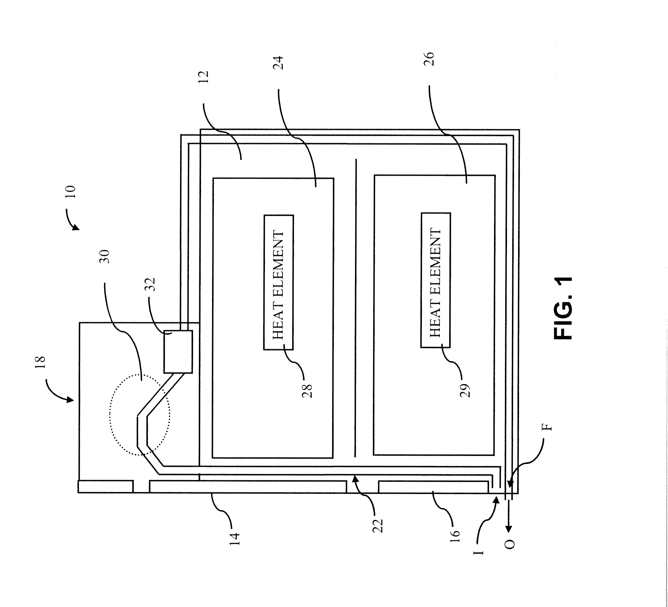
[0025]Referring to FIG. 1, illustrated is an exemplary appliance according to at least one aspect of the present disclosure, such as a double wall oven 10. The double wall oven 10 includes an outer housing 12 defining an interior space in which food or other items to be heated are placed, and upper and lower doors 14 and 16 for providing access to said interior space inside of which one or more heating elements are located. An electronics bay 18 is located on an upper side 24 of the oven 10 and contains various electronic controls for operation of the oven 10. Although an oven appliance 10 is illustrated, the present disclosure is not limited to any one type of appliance. Accordingly, basic features are described in the oven 10 briefly as an exemplary aspect of some embodiments herein.

[0026]For example, the oven 10 includes one or more cooling air-flow passageways 22 for circulating air around the oven chassis and the electronics bay 18. The passageway 22 defines a flow path F for t...


PUM


Abstract

Apparatus and methods are disclosed to measure airflow within a chassis-cooling pathway of an appliance. The rate of airflow is determined based on the differential heating among a pair of sensor devices, such as thermistors, transistors, diodes or resistive thermal devices operating at distinctly different power levels. The appliance utilizes the calculated airflow rate to perform safety-related tasks, such as de-energizing heating elements when low or no airflow is detected.

Description

BACKGROUND OF THE DISCLOSURE[0001]The present disclosure generally relates to appliances, and more particularly, to detecting airflow, and / or measuring airflow velocity, in a cooling pathway of an appliance.[0002]Appliances such as cooking ranges are widely used. A cooking range typically includes an oven. The oven typically has a front-opening access door, and at least one heating element for heating up the inside of the oven cavity. As is known in the art, when energized, the heating element can heat up the inside of the oven cavity to a relatively high cooking temperature chosen by a user. Also as is known in the art, the cooking range often has a fan which is used to cool a component of the oven, such as the front-opening access door, or a heat sensitive component of the oven such as an electronic controller or display unit, to a temperature which is lower than the chosen cooking temperature. Some certification institutions, such as Underwriters Laboratories Inc. (UL), require t...

Claims


Application Information

Patent Timeline
Patent Type & Authority Applications(United States)
IPC IPC(8): G01F1/688F24B5/02
CPCF24B5/02G01F1/696G01F1/688F24C15/006
Inventor BACH, JAMES CARTER
Owner HAIER US APPLIANCE SOLUTIONS INC
Why Eureka
Try Eureka