Multi-way doherty amplifier

a doherty amplifier and multi-way technology, applied in the direction of amplifiers, amplifier modifications to reduce detrimental impedence, electrical equipment, etc., can solve the problems of difficult control of the quality or performance of such amplifiers in mass production, amplifiers are not used on a large scale, time-consuming tasks, etc., to improve the design and performance of a 3-way doherty amplifier, and reduce the overall size of the 3-way doherty design. , the effect of improving

Active Publication Date: 2010-07-29
AMPLEON NETHERLANDS
View PDF15 Cites 12 Cited by
  • Summary
  • Abstract
  • Description
  • Claims
  • Application Information

AI Technical Summary

Benefits of technology

[0006]The inventors now propose an alternative approach for designing a multi-way Doherty amplifier. The inventors therefore propose a circuit as claimed in claim 1. The integrated two-way Doherty amplifier is a pre-tested and optimized building block and is used in the invention as if it were a conventional discrete transistor. The multi-way Doherty amplifier design of the invention therefore has a high degree of similarity to a conventional two-way design, and requires less design effort than a two-way Doherty amplifier implemented with discrete transistors. Also, the integrated two-way Doherty amplifier takes up smaller space than a two-way Doherty amplifier implemented with discrete transistors. In addition, the use of an integrated 2-way Doherty amplifier improves the consistence in behavior and in performance of a mass-produced 3-way Doherty amplifier of the invention, owing to fewer components being involved in the design. Furthermore, the design of the Doherty amplifier in the circuit of the invention can be customized in that type, brand, or size of the further peak stage can be chosen from commercially available components and from a variety of conventional technologies (hybrids, PCBs, power devices, etc.), dependent on the customer's needs. For example, the size of the peak stage, integrated in the two-way Doherty amplifier semiconductor device, and the size of the further peak stage, separately implemented in another semiconductor device, can be chosen as being different so as to have the desired behavior. Also, the integrated 2-way Doherty amplifier has the advantage that the main stage therein is kept cooler than if it were a separate semiconductor device. The main stage of a Doherty amplifier dissipates more power than the peak stage. The main stage therefore will generate more heat than the peak stage. As a result of the main stage being integrated on the same die as the peak stage of the integrated Doherty amplifier, twice the area is available for main stage to lose the heat it is generating, e.g., to a heat sink. Accordingly, the main stage of the integrated Doherty amplifier keeps cooler. It is common knowledge in the field of integrated circuitry devices that lowering the temperature of the device by 10° increases the life expectancy of the device by a factor of two.
[0008]In another embodiment of the invention relating to a 3-way Doherty amplifier, a first output of the two-way integrated Doherty amplifier is connected to an output node of the 3-way Doherty amplifier via a first λ / 2 line or via another structure implementing a 180° phase shift, and a second output of the further peak stage is connected to the output node via a second λ / 2 line or via a further structure implementing a 180° phase shift. In this configuration, the first and second λ / 2 lines provide the required impedance transformation and take care of the “in-phase” operation of the two-way integrated Doherty amplifier and the further peak stage. At the same time, these lines allow arranging in a proper manner the design and the PCB layout and physically combining two, even very large packaged devices in parallel without loss of performance.
[0009]A further improvement of a 3-way Doherty amplifier design and performance can be achieved if the integrated 2-way Doherty amplifier and the further peak stage are arranged on the same metal flange in a so-called push-pull package, having four RF terminals or leads. This design further decreases the overall size of the 3-way Doherty design and, more importantly, improves the consistence of the behavior and performance of the amplifier in mass production. This especially holds if all semiconductor dies involved are produced within the same wafer in a single production cycle, thus giving rise to very high level of parameter similarity or identity. Also, operation of all semiconductor dies arranged on the same flange, or heat sink, will provide very consistent temperature difference between all dies of the 3-way Doherty system of the invention, and also improve product consistence (e.g., phase and amplitude of combined signals) in mass production. For more background on push-pull packages see, e.g., US published patent application 20070103237, herein incorporated by reference.

Problems solved by technology

However, designing a three-way Doherty amplifier that uses discrete transistors is a very time-consuming task and the quality or performance of such an amplifier is difficult to control in mass production.
Under laboratory conditions, a three-way Doherty amplifier shows superior efficiency at 12 dB back-off levels, but these amplifiers are not used on a large scale owing to the complexity of the design and the space needed to implement the design.
However, the design of a multi-way asymmetrical integrated Doherty amplifier, using the approach described in the publication of Blednov and van der Zanden, is a challenging task owing to the difficulties involved in properly dividing the input power between the main stage, the first peak stage, and the second peak stage and further in combining power outputs of several peak devices of different sizes in an MMIC (Monolithic Microwave Integrated Circuit) environment.
Also, the integrated two-way Doherty amplifier takes up smaller space than a two-way Doherty amplifier implemented with discrete transistors.

Method used


Image

  • Multi-way doherty amplifier
  • Multi-way doherty amplifier

Examples


Embodiment Construction

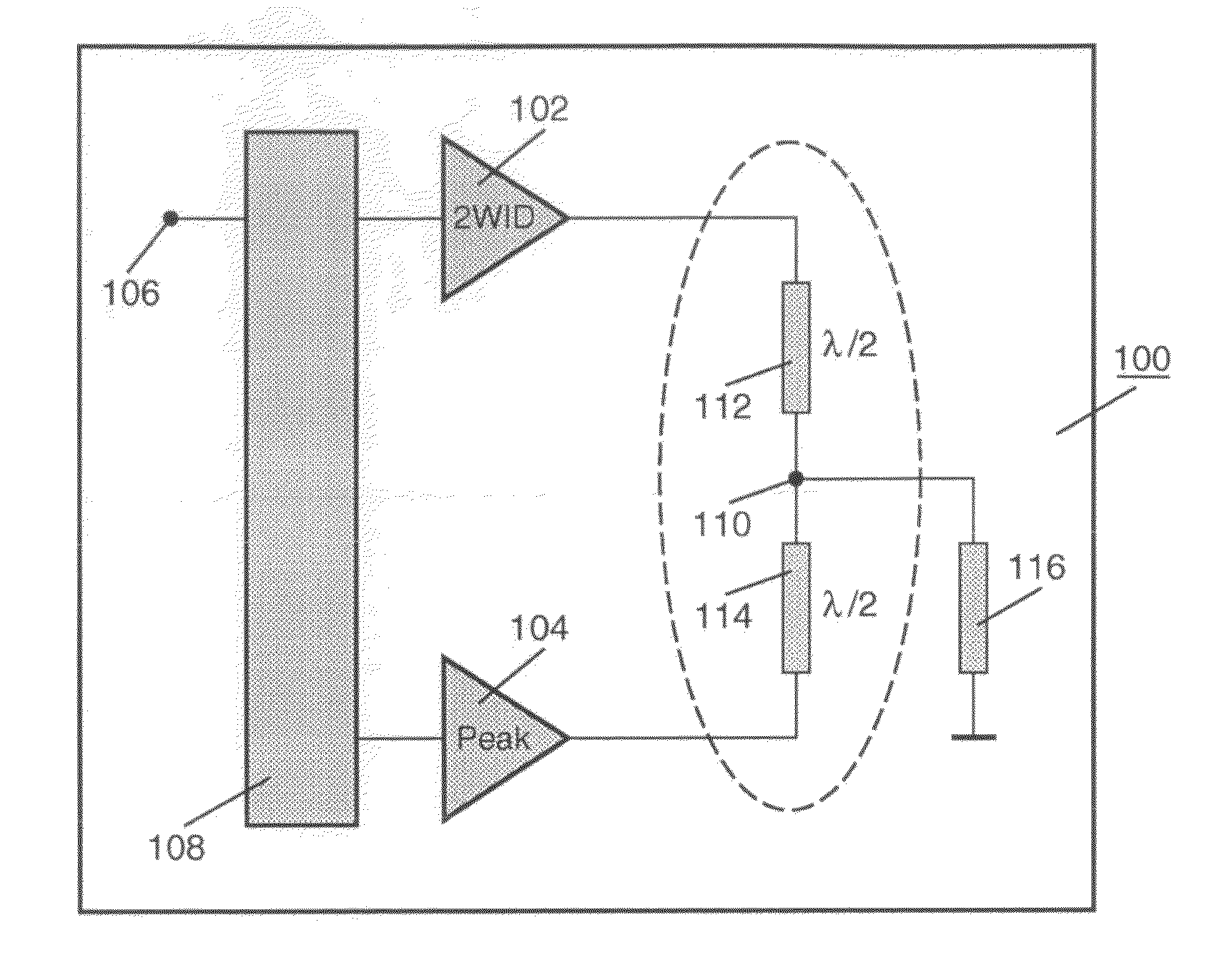
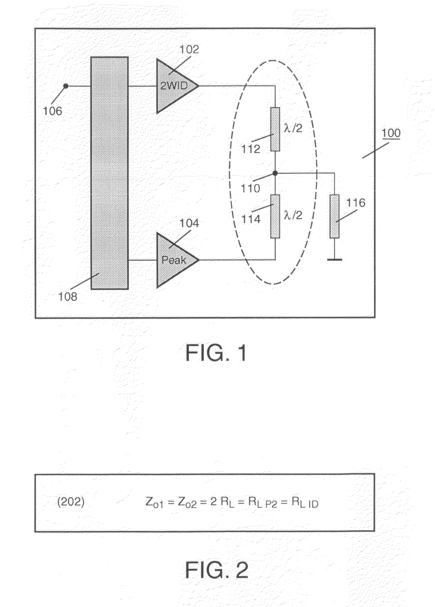
[0013]FIG. 1 is a diagram of an electronic circuit 100 with a multi-way Doherty amplifier that comprises a two-way Doherty amplifier 102, having a main stage and a first peak stage and integrated in a semiconductor device, and at least one further peak stage 104 implemented with a discrete power transistor. Inputs of amplifier 102 and of further peak stage 104 are connected to an input node 106 via an input network 108. Input network 108 comprises, for example, a hybrid coupler between input node 106 and the inputs of amplifiers 102 and 104. Alternatively, input network comprises a λ / 4 line of specific impedance between the inputs of amplifiers 102 and 104 so as to implement a 90° phase shift. An output of integrated two-way Doherty amplifier 102 is connected to an output node 110 via a first λ / 2 line 112. An output of further peak stage 104 is connected to output node 110 via a second λ / 2 line 114. Output node 110 is connected to a load resistance 116. Lines 112 and 114 form an out...


PUM


Abstract

An electronic circuit has a multi-way Doherty amplifier. The multi-way Doherty amplifier comprises a two-way Doherty amplifier with a main stage and a first peak stage that are integrated in a semiconductor device; and at least one further peak stage implemented with a discrete power transistor.

Description

FIELD OF THE INVENTION[0001]The invention relates to an electronic circuit with a multi-way Doherty amplifier.BACKGROUND ART[0002]As known, a classical Doherty amplifier has two amplifying devices arranged in parallel and of the same power capability. The first one of the devices (main stage) operates in a class-AB amplifier mode and the second one (peak stage) operates in a class-C amplifier mode. These devices are separated at their inputs and at their outputs by 90° phase-shifting networks. The output phase-shifting network has a specific characteristic impedance Z0 which must be equal to the optimal load impedance RLm of the main stage. The input signal is split so as to drive the two amplifiers, and a summing network, known as an “impedance inverter” or a “Doherty combiner”, is operative to: a) combine the two output signals, b) to correct for phase differences between the two output signals, and c) to provide an inverted impedance at the output of the Doherty amplifier with re...

Claims


Application Information

Patent Timeline
Patent Type & Authority Applications(United States)
IPC IPC(8): H03F3/68
CPCH03F1/08H03F1/0288H03F2200/408
Inventor BLEDNOV, IGORVAN DER ZANDEN, JOSEPHUS H. B.
Owner AMPLEON NETHERLANDS
Why Eureka
Try Eureka