LED light source

a technology of led light source and led load, which is applied in the direction of electroluminescent light source, electric lighting source, and use of semiconductors. it can solve the problems of reducing circuit efficiency, affecting the sense of current signal, and affecting the effect of circuit efficiency

Inactive Publication Date: 2015-12-08
KONINK PHILIPS ELECTRONICS NV +1
View PDF4 Cites 9 Cited by
  • Summary
  • Abstract
  • Description
  • Claims
  • Application Information

AI Technical Summary

Benefits of technology

[0011]It is an object of the present invention to provide a LED light source in which the control of the currents through the LED loads is such that gaps and spikes in the current drawn from the power supply as well as light flicker and power dissipation are avoided, also in the case of dimmed operation of the LED light source.
[0022]In a LED light source according to the invention, the currents through the LED loads and the control strings are controlled by means of current sensing as well as by means of the voltage sensing circuits. It has been found that the combination of these two control mechanisms provides excellent control of the currents through the control strings over the entire dimming range.
[0023]Good results have been obtained for embodiments of a LED light source according to the invention, wherein the impedances in the control strings are comprised in a series arrangement coupled between the transistor comprised in the first control string and the second output terminal of the rectifier. In this way, effective control of the currents through the LED loads and the control strings is possible while the control circuitry is very simple.
[0026]In a preferred embodiment of a LED light source according to the invention, the global current control circuit comprises a modulator for modulating the current through the LED loads with a frequency 2 f such that the instantaneous value of the current is decreased when the instantaneous value of the low frequency AC supply voltage increases and the instantaneous value of the current is increased when the instantaneous value of the low frequency AC supply voltage decreases. As already pointed out here-above some ways of controlling the current through the LED loads cause the current to increase, when the number of LED loads conducting current increases. In other words, the more LED loads conduct current, the higher this current is. In fact, in order to reduce light flicker, the opposite is required. By means of modulating the current through the LED loads, via the global current control circuit, the current increasing effect of the phase current stacking control can be counteracted.
[0028]This way of dimming is more in particular effective, in case the LED light source comprises a series arrangement of a switch and a capacitor coupled between the output terminals of the rectifier and control circuitry (VIII) for rendering the switch conductive in case the instantaneous value of the low frequency AC supply voltage drops below a reference value.The capacitor ensures that the supply voltage of the LED loads never drops to zero and that at least part of the LED loads always carry a current. The magnitude of this current can be adjusted by adjusting the voltage present at the control electrodes of the transistors comprised in the control strings via the global current control circuit. More in particular, in case the LED light source is used with a phase cut dimmer, the global current control circuit may comprise circuitry for adjusting the voltage at the control electrodes of the transistors in the controllable current regulators in dependency of the adjusted phase angle of the phase cut dimmer. In this way compatibility of the LED light source with phase cut dimmers is realized in an effective way.

Problems solved by technology

Both these methods suffer from the drawback that the forward voltages of LED loads that are nominally identical show a certain amount of spread.
Consequently overlaps or gaps between the conduction intervals of neighboring control strings occur, causing undesirable current spikes and valleys that also reduce the circuit efficiency.
Said method suffers from the drawback that the sensed current signal may become very weak, when the LED light source is in dimmed operation.
However, because of small differences in the characteristics of the transistors comprised in the first and second control string and the unequality of the conducted currents, the emitter voltages are not quite identical.
A drawback of this method is that the current can never be completely pinched off, but can only be reduced.
The fact that the currents through the control strings cannot be decreased to zero and that these unwanted currents depend on the dim level is a disadvantage of this way of controlling the currents through the LED loads and the control strings.

Method used


Image

  • LED light source
  • LED light source
  • LED light source

Examples


Embodiment Construction

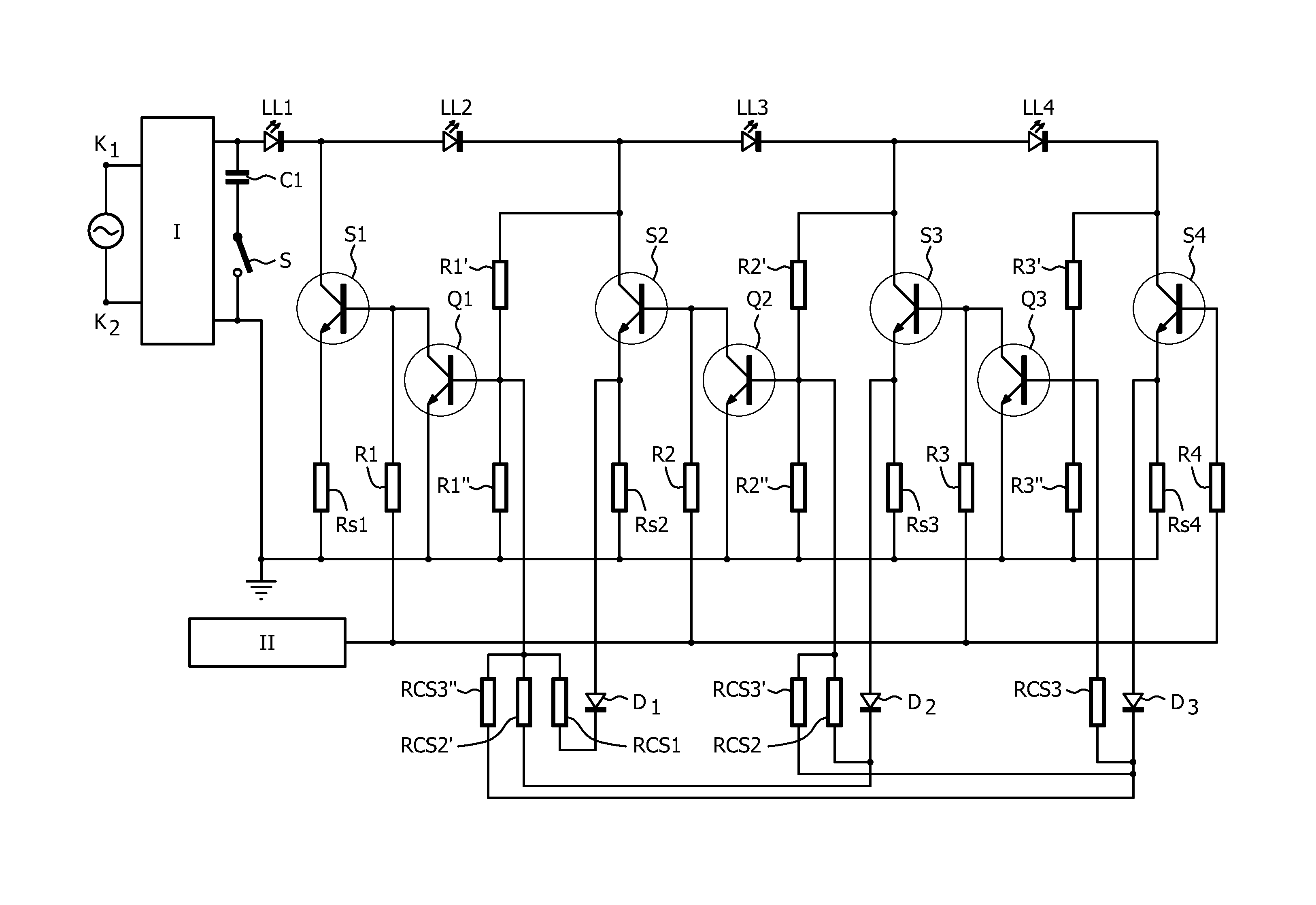
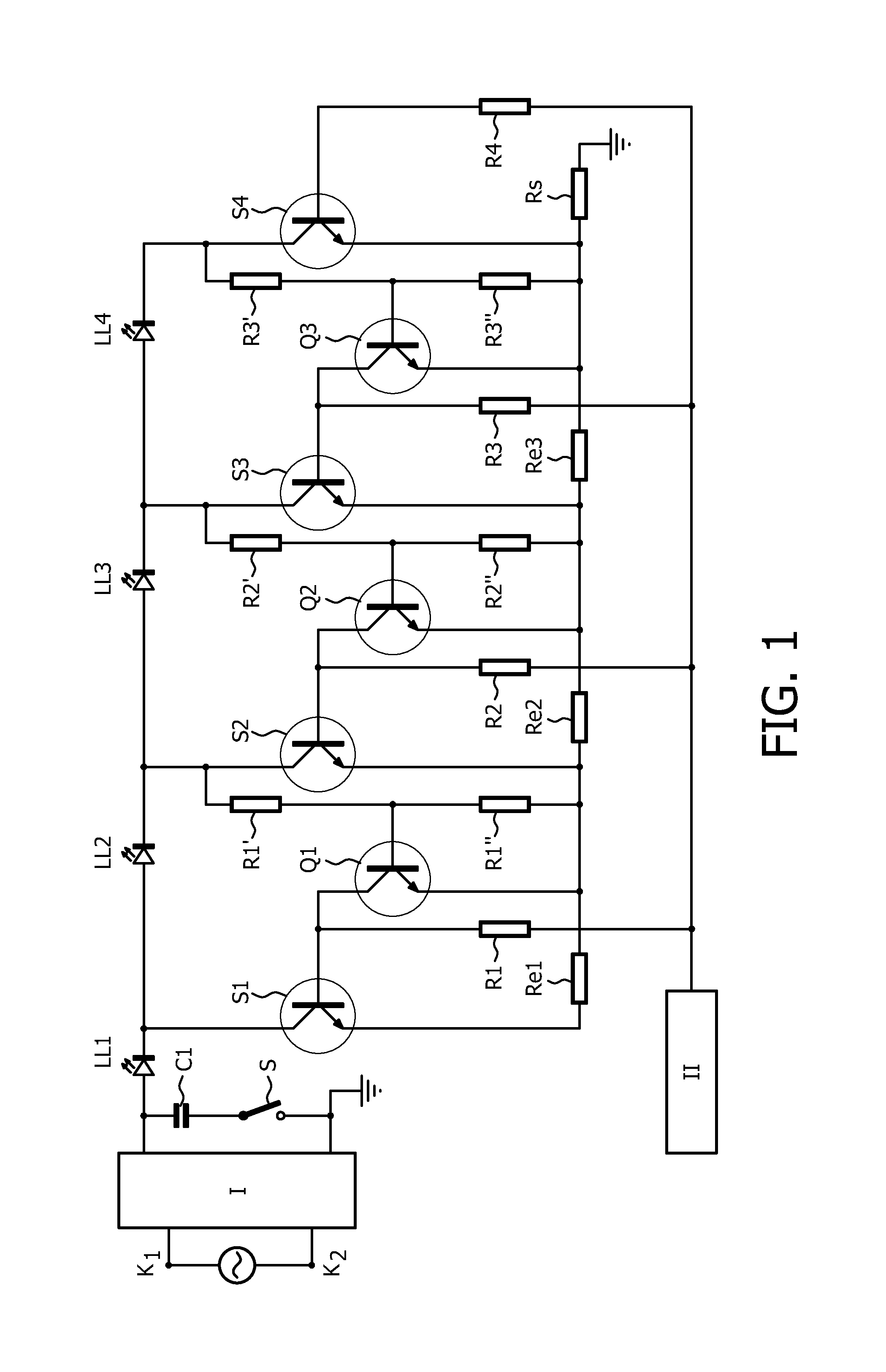
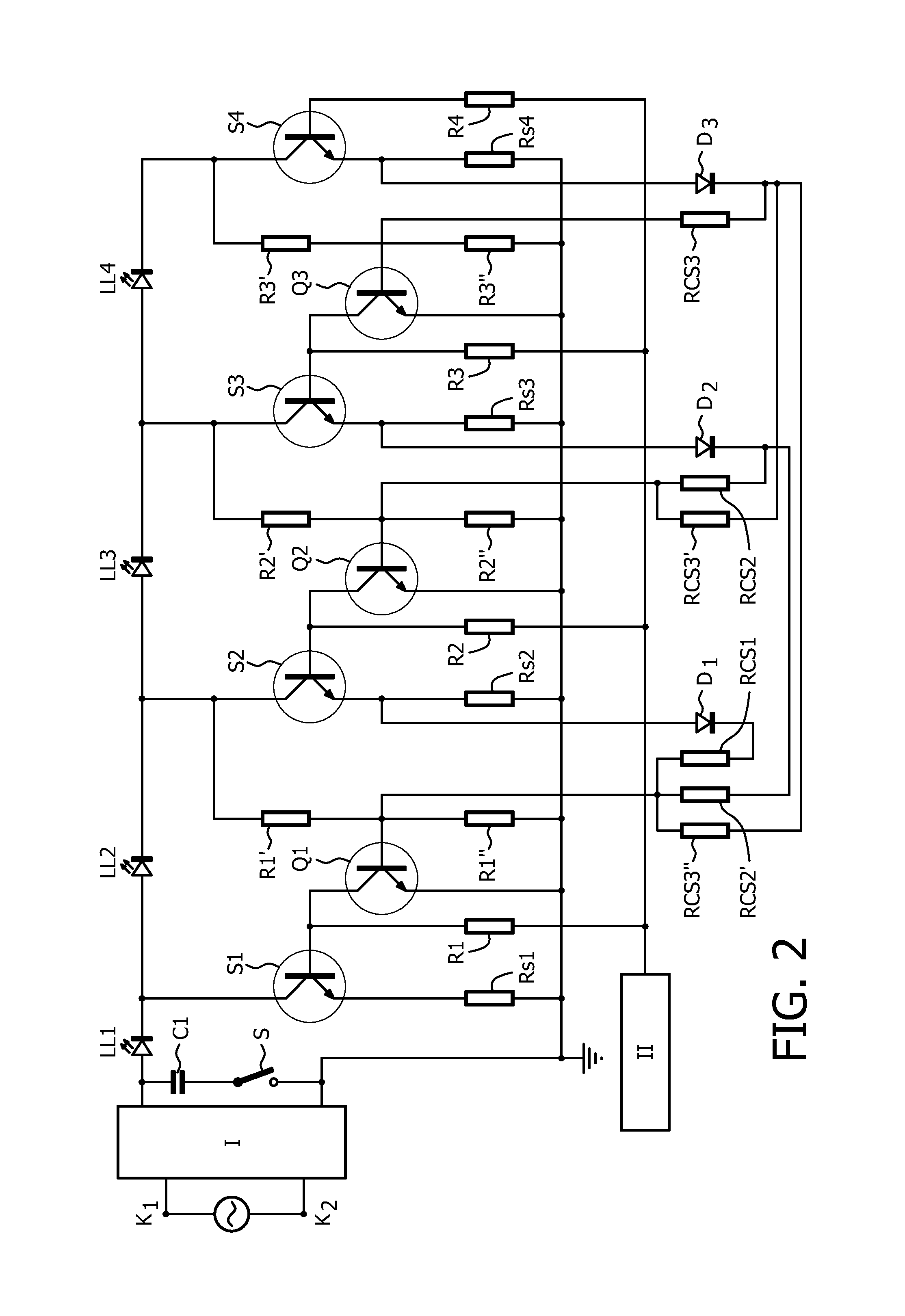
[0034]In FIGS. 1, K1 and K2 are respectively a first and a second input terminal for connection to a supply voltage source supplying a low frequency AC supply voltage with frequency f, such as the European or American mains voltage. Circuit part I is a rectifier for rectifying the low frequency AC supply voltage.

[0035]Output terminals of the rectifier are connected by means of a series arrangement of a capacitor C1 and a switch S.

[0036]LL1, LL2, LL3 and LL4, transistor S4 and resistor Rs together form a series arrangement comprising N LED loads coupled between a first and a second output terminal of the rectifier. Transistor S1 together with resistor Re1 form a first control string. Similarly, transistor S2 and resistor Re2 form a second control string, transistor S3 and resistor Re3 form a third control string, and transistor S4 and resistor Rs form a fourth control string.

[0037]The transistors can for instance be unipolar transistors, bipolar transistors, Darlington transistors or...


PUM


Abstract

A string of LED loads is supplied by means of a rectified mains voltage. A cathode of each LED load is coupled to ground by means of a string. The strings are made conductive and non-conductive one by one in dependency of the instantaneous value of the rectified mains using both voltage and current sensing.

Description

FIELD OF THE INVENTION[0001]The invention relates to a cheap and simple LED light source comprising N LED loads that is directly connectable to a supply source supplying a low frequency AC voltage such as the mains supply.BACKGROUND OF THE INVENTION[0002]Such a LED light source is known from U.S. Pat. No. 7,081,722 B1. The LED loads are LED arrays comprising series arrangements and possibly parallel arrangements of individual LEDs. The known LED light source comprises a rectifier for rectifying the low frequency AC supply voltage. A series arrangement comprising the N LED loads is connected to output terminals of the rectifier. During operation a periodical DC voltage with an instantaneous value varying between zero Volt and a maximum amplitude is present between the output terminals of the rectifier. The known LED light source is equipped with control means for subsequently making the LED loads conduct a current, one by one and starting with a first LED load that is closest to a fi...

Claims


Application Information

Patent Timeline
Patent Type & Authority Patents(United States)
IPC IPC(8): H05B37/00H05B33/08H05B44/00
CPCH05B33/0845H05B33/083H05B33/0812H05B33/0815Y02B20/347Y02B20/348H05B45/48H05B45/3575Y02B20/30H05B45/31H05B45/30H05B47/10
Inventor TAO, HAIMINKAHLMAN, HENRICUS MARIUS JOSEPH MARIABLANKEN, PIETER GERRITKURT, RALPH
Owner KONINK PHILIPS ELECTRONICS NV
Why Eureka
Try Eureka