Apparatus and method for controlling the motor power

a technology of motor power and apparatus, applied in the direction of electrical equipment, electric motor control, transmission systems, etc., can solve the problems of inequal distribution of power losses, conduction losses, and loss, and achieve equal power dissipation in the switch module, high power dissipation, and reduced local heating

Inactive Publication Date: 2011-06-14
KONE CORP
View PDF15 Cites 10 Cited by
  • Summary
  • Abstract
  • Description
  • Claims
  • Application Information

AI Technical Summary

Benefits of technology

[0037]When the motor is rotating at a low speed but a high momentary torque is required, as in an elevator drive during acceleration, the current through the load-side inverter is substantially larger than the current through the mains inverter. In this situation, high power dissipation occurs in the bidirectional switches of the load-side inverter and the switch module is intensively heated in the vicinity of the switches. When the phase current of the load-side inverter is distributed among several parallel-connected bidirectional switches and these bidirectional switches are placed at a distance from each other, the power dissipation in the switch modules is equalized and local heating is reduced. As the switch modules are more equally heated, they can be designed for larger currents or correspondingly smaller switch modules can be used for controlling the same current, thus reducing the costs. This method provides an advantage especially in drives in which the momentary current requirement of the load-side inverter is considerably higher than the long-time average current requirement. This type of drives include e.g. elevator drives, in which a high momentary current is needed for acceleration.
[0038]In motor drives requiring a high torque with a low motor current frequency, such as e.g. in an elevator drive during fine positioning of the elevator car at a landing, the bidirectional switches of the same phase of the load-side inverter conduct a large current for a long time. Therefore, the switch module is intensively heated in the vicinity of the bidirectional switches. If the current is distributed between the outermost bidirectional switches of the three-phase switch module via parallel connection, the switch module will be more equally heated. Thus, it is possible to use semiconductors designed for a smaller current. Power dissipation can be further equalized by distributing the parallel-connected bidirectional switches among several switch modules.
[0039]If the semiconductor module is heated in a point-like manner, then the heat sink also receives more heat in the vicinity of the point-like heat source. In this situation, the heat sink can not transfer heat efficiently from the switch module to the environment. When the switch modules are equally heated, the heat sink is also more evenly heated and transfers heat more efficiently to the environment. As the heating occurs uniformly, it is possible to use a smaller heat sink and fan, thereby reducing the size of the power control apparatus. This provides an advantage especially in applications where space is a critical factor. E.g. in elevator systems, a transition to solutions without counterweight in which the power control apparatus is often disposed in the elevator shaft has taken place, a small size of the power control apparatus being therefore desirable.
[0040]In the power control apparatus of the invention, it is possible to use commercial three-phase semiconductor modules which contain three bidirectional switches. In conjunction with the modules it is possible to connect an intermediate-circuit energy source and a heat sink, and thus separate power control units can be formed according to the invention. By modularly combining such power control units, it is possible to construct different power control apparatuses. For example, a DC-DC chopper can be formed by using a similar power control unit. When the number of converters in the power control apparatus increases, the switches of different converters can be further distributed among different switch modules into several different combinations, power dissipation between the modules can be further equalized and the current capacity of the modules improved. By modularly combining identical power control units, an advantage is also achieved regarding the cost of large production series.
[0041]When at least one switch module comprised in the power control apparatus contains bidirectional switches of at least two different converters, said converters belonging to said power control apparatus, and bidirectional switches of a first converter in the aforesaid switch module are fitted interjacently with bidirectional switches of a second inverter in the switch module, the switch module is more equally heated than e.g. in prior-art applications where the switch modules belonging to the power control apparatus comprise bidirectional switches of only one converter. For example, if several bidirectional switches are connected in parallel to the phases of one converter, such as a three-phase load-side inverter, in such manner that the phase current is distributed among the parallel-connected bidirectional switches, and if the bidirectional switches of the load-side inverter are so fitted in different switch modules that one module contains bidirectional switches of at least two different phases of the load-side inverter, then, in a certain situation in the control, the adjacently fitted bidirectional switches of different phases of the said switch module still carry simultaneously a large momentary current. If e.g. the load-side inverter feeds a symmetric load, such as star-connected motor windings, in a certain situation in the control, when the phase current in one phase of the load-side inverter is near zero, the other two phases of the load-side inverter carry momentarily a large current. When at least two bidirectional switches of different phases of the load-side inverter are now fitted mutually adjacently in the switch module, a large current flows momentarily in the adjacently fitted bidirectional switches, and consequently the switch module is locally heated in the area of these bidirectional switches. The heat sink can thus not transfer heat effectively from the switch module to the environment, which limits the current capacity of the switch module. If instead the aforesaid bidirectional switches of the load-side inverter were fitted, as proposed in the invention, e.g. interjacently with the bidirectional switches of another converter, such as a mains inverter, comprised in the same power control apparatus, then the switch module would be more equally heated, the heat sink would transfer heat more effectively from the switch module to the environment, and the current capacity of the switch would be increased.
[0042]In an embodiment of the invention where the power control apparatus comprises a load-side inverter and a mains inverter, two parallel-connected bidirectional switches can be fitted in each phase of the load-side inverter and a corresponding switch can be fitted in each phase of the mains inverter, as proposed in the invention. In this case, the power control apparatus can be formed from three switch modules each containing three bidirectional switches, in such manner that the middle switch of each switch module is fitted in a phase of the mains inverter and the outermost bidirectional switches are fitted as a parallel connection in a phase of the load-side inverter. Because in many drives, such as in an elevator drive at low speeds, the bidirectional switches of the load-side inverter are heated more than the bidirectional switches of the mains inverter, this type of switch topology can be used to improve the current capacity of the power control apparatus.

Problems solved by technology

Therefore, the power losses are unequally distributed between the bidirectional switches of the load-side inverter, and the bidirectional switch having the largest current is heated most.
In this type of semiconductors there occur losses, which can be divided into conduction losses and switching losses.
Conduction losses occur when a current is flowing through a conducting semiconductor.
Switching losses occur in connection with the switching action of the semiconductor, both when the semiconductor is switched on into the conducting state and when its is switched off.
If the duration of the current is so short that only the semiconductor module and possibly part of the heat sink become heated, then increasing the size of the heat sink will not increase the current capacity of the semiconductor module, but a semiconductor module having a lower power dissipation and designed for larger currents is needed.
This increases the costs.
In this case the heat sink is again unable to dissipate enough heat to the environment, but the local heating of the semiconductor module caused by the point-like power dissipation source limits the current capacity of the semiconductor module.
This has the consequence that the design current capacity of the semiconductor module has to be increased if necessary to a semiconductor module having a lower power dissipation, which means increasing the costs.

Method used


Image

  • Apparatus and method for controlling the motor power
  • Apparatus and method for controlling the motor power
  • Apparatus and method for controlling the motor power

Examples


Embodiment Construction

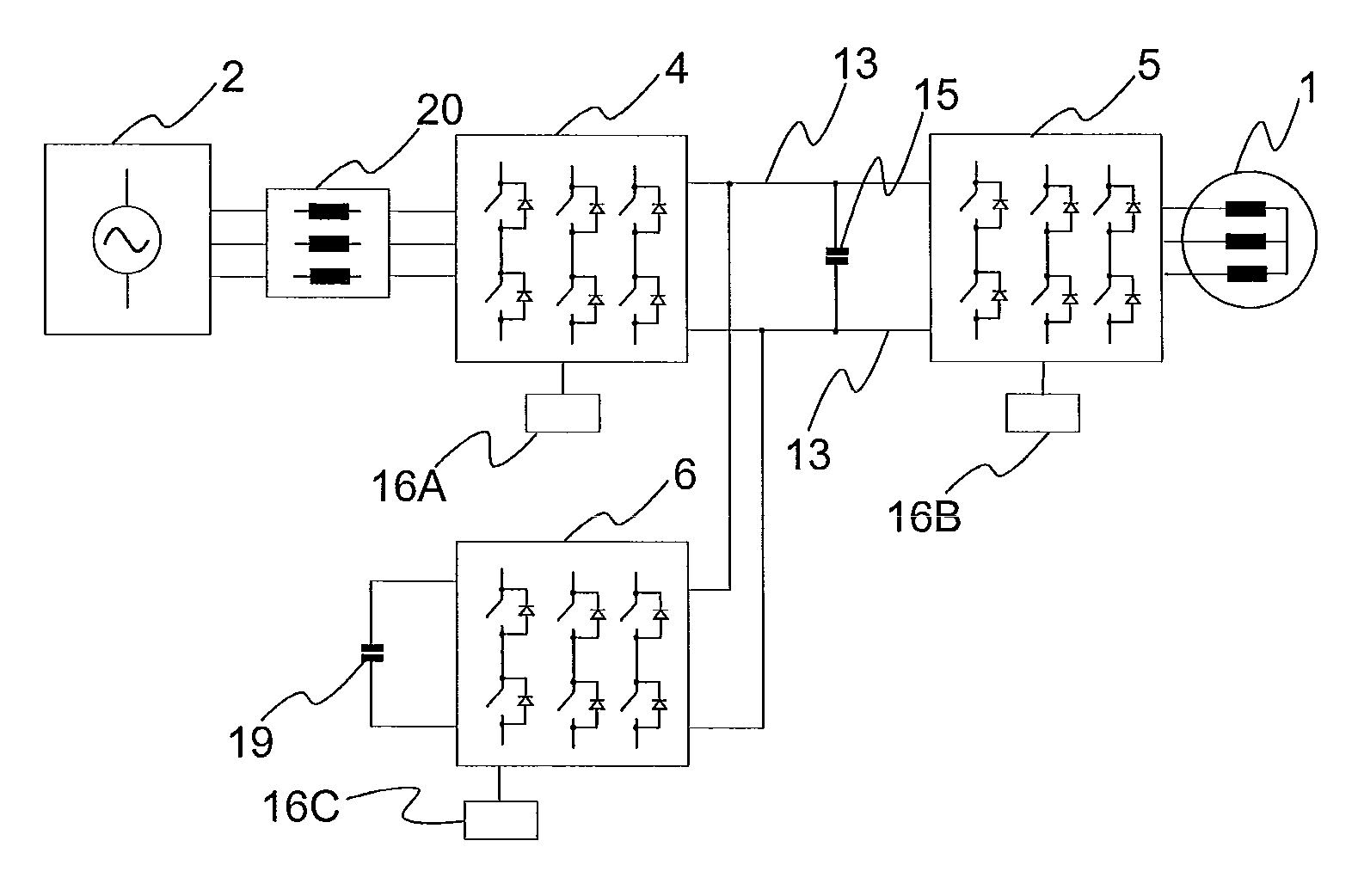
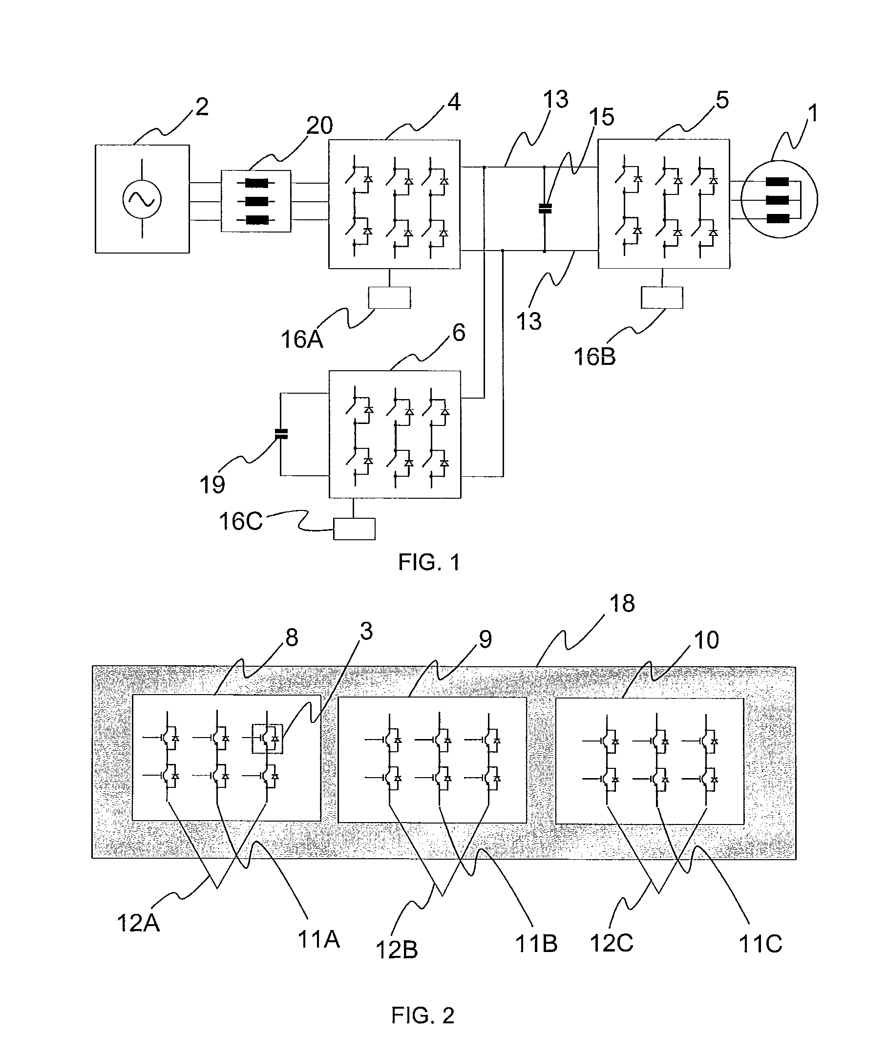
[0049]FIG. 1 shows a power control apparatus according to the invention. The power control apparatus comprises a mains inverter 4 and, in connection with the mains inverter, an inductor unit 20. The mains inverter and an load-side inverter 5 are connected to a common direct-voltage intermediate circuit 13. The direct-voltage intermediate circuit has a capacitor 15 as an energy storage. Connected to the direct-voltage intermediate circuit is additionally a DC-DC chopper 6, which supplies energy between establish direct-voltage intermediate circuit 13 and the energy source 19. The load-side inverter 5 supplies a motor 1 with a voltage varying in frequency and amplitude. During acceleration of the motor, the power control apparatus, controlled by mains inverter control 16A, supplies power from the mains network 2 via the mains inverter 4 to the direct-voltage intermediate circuit 13 and further, controlled by load-side inverter control 16B, via the load-side inverter 5 to the motor 1. ...


PUM


Abstract

The invention concerns a power control apparatus and a method for supplying power between an electric machine and an energy source. The power control apparatus contains at least two converters comprising a plurality of switches, at least some of which switches belong to a set of switch modules comprising a plurality of switches. In the method of the invention, a first set of switches belonging to at least two different modules and arranged to form a first converter is controlled by a first converter control, and a second set of switches arranged to form a second converter is controlled by a second converter control.

Description

[0001]This application is a Continuation of PCT / FI2008 / 000007 filed on Jan. 17, 2008, and claims priority under 35 U.S.C. §119(a) on Patent Application No. 20070136 filed in Finland on Feb. 15, 2007, respectively, all of which are hereby expressly incorporated by reference into the present application.FIELD OF THE INVENTION[0002]The present invention relates to a power control apparatus as defined in the preamble of claim 1 and to a method as defined in the preamble of claim 15 for controlling a power control apparatus.PRIOR ART[0003]Modern motor power control apparatuses supply power between a supply network and an electric power machine, such as an electric motor, in both directions. The control apparatus contains a mains inverter, which is used to convert the supply network voltage into a direct voltage, and a load-side inverter by means of which the direct voltage is converted into an alternating voltage of varying amplitude and frequency for the electric motor. The load-side in...

Claims


Application Information

Patent Timeline
Patent Type & Authority Patents(United States)
IPC IPC(8): H02J3/00
CPCB66B1/30H01L23/36H02P29/0088Y10T307/707H01L2924/0002H01L2924/00H02P29/68B66B1/28H02M5/44H02P27/04
Inventor JAHKONEN, PEKKA
Owner KONE CORP
Why Eureka
Try Eureka