
Positive displacement flow meter

a flowmeter and positive displacement technology, applied in the direction of liquid/fluent solid measurement, instruments, rotary piston engines, etc., can solve the problems of vibration, backlash, excessive noise, existing flowmeters,

Inactive Publication Date: 2013-01-31
LUKER GRAHAM JAMES
View PDF7 Cites 3 Cited by
  • Summary
  • Abstract
  • Description
  • Claims
  • Application Information

AI Technical Summary

Benefits of technology

The patent describes a new type of flowmeter that helps to improve the way liquids and gases are measured. The flowmeter has two rotors that rotate inside a housing, and they are designed to work together to measure the flow of fluid passing through the meter. Each rotor has special features, like concave surfaces, and they are fitted with magnets to create signals that indicate how fast the rotors are spinning and how much fluid is flowing. This information helps to accurately measure the flow of liquids and gases in real-time.

Problems solved by technology

Such existing flowmeters have a number of disadvantages however.
The oval two lobe design at least in large size flowmeters produces out-of-balance forces which cause vibration, backlash and excessive noise.

Method used


Image

  • Positive displacement flow meter
  • Positive displacement flow meter

Examples


Embodiment Construction

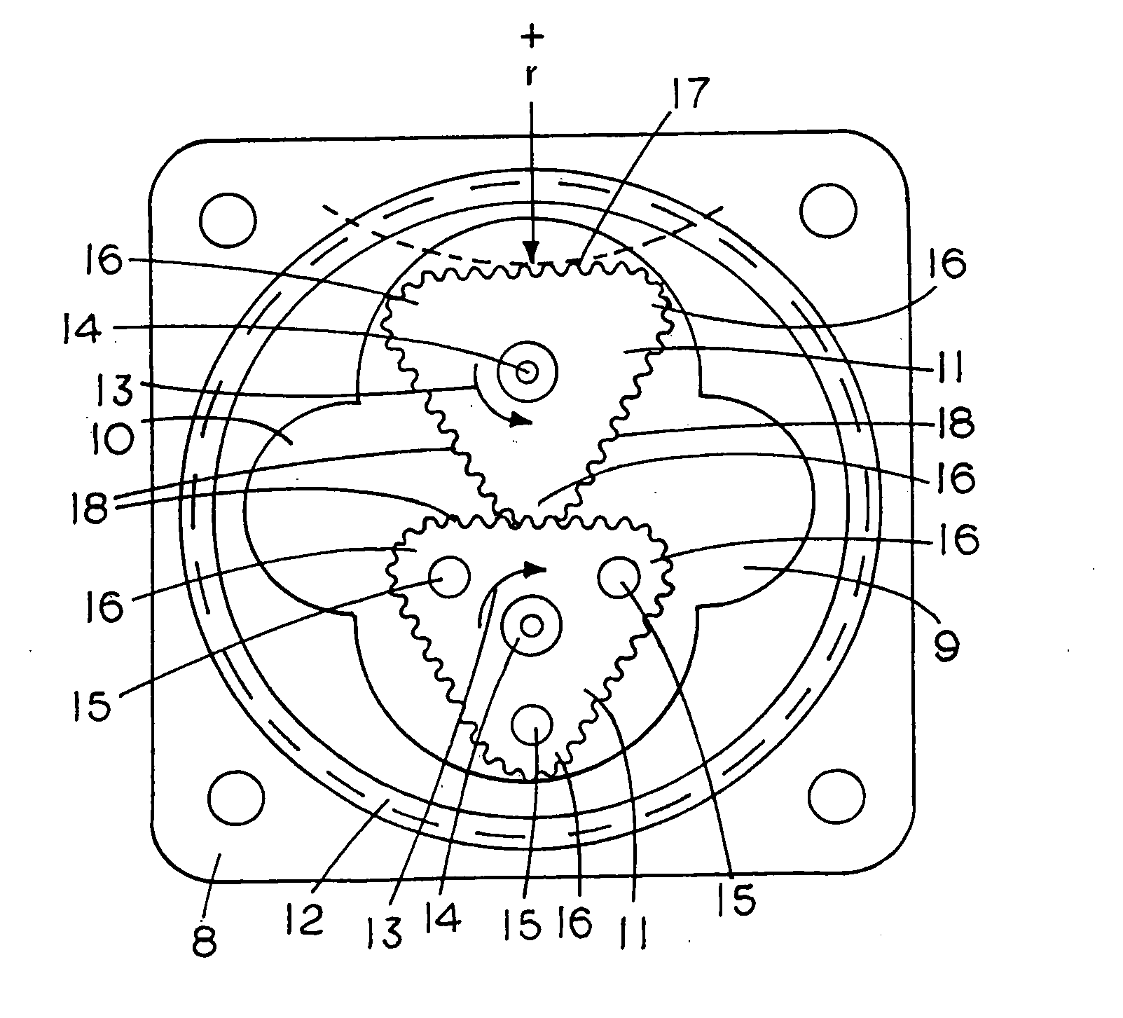
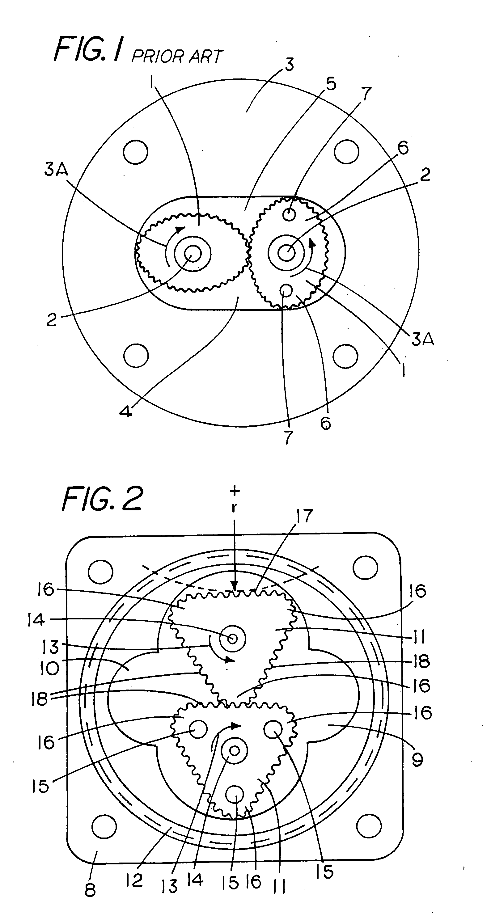
[0010]One currently preferred embodiment of the invention will now be described with reference to the attached FIG. 2 which shows in plan view an open flowmeter housing with meshed rotor assembly according to the invention.

[0011]There is a housing 8 from which the cover (not shown) has been removed to show fluid inlet and outlet chambers 9, 10 defined on each side of meshed rotors 11. There is also a fluid seal 12 shown surrounding the chambers. The rotors are rotatably offset by 60 degrees as shown and meshed together in a relationship which causes said rotors to rotate in the direction of arrows 13 about spaced apart parallel axis 14 as fluid passed through the meter from the inlet chamber 9 to the outlet chamber 10. With this embodiment the bottom rotor as shown has implanted magnets 15 which activate an external reed switch, hall effect device or other like means (not shown) to generate signals indicative of rotor speed and thus the volume of fluid flow through the meter.

[0012]I...


PUM


Abstract

There is a positive displacement flowmeter having a pair of rotors 11 rotatable on spaced apart parallel axis 14 within a housing 8 between inlet and outlet chambers 9, 10. The rotors have gear teeth 18 and are meshed together to rotate in accordance with volumetric fluid flow through the meter from the inlet chamber 9 to the outlet chamber 10. Each of the rotors has three lobes with rotor profiles between adjacent lobes being concave.

Description

FIELD OF THE INVENTION[0001]This invention relates to apparatus for flow measurement. More particularly, although not exclusively, it discloses improvements in positive displacement flowmeters.BACKGROUND OF THE INVENTION[0002]Existing positive displacement flowmeters, as shown for example in FIG. 1, typically include a pair of oval shaped rotors 1 rotatable on spaced apart parallel axis 2 within a housing 3. The rotors are rotatably offset by 90 degrees and meshed together with straight-cut gears in a critical relationship which causes said rotors to rotate in the direction of arrows 3A as fluid passes through from an inlet chamber 4 to an outlet chamber 5. The speed of rotation of the rotors is related to and indicative of the volume flow through the meter per unit of time. Each oval rotor passes two displacements of fluid per revolution. The lobes 6 on one of the rotors are fitted with magnets 7 which activate an external reed switch, hall effect device or other means (not shown) ...

Claims


Application Information

Patent Timeline
Patent Type & Authority Applications(United States)
IPC IPC(8): G01F3/08F01C1/18
CPCG01F3/08F04C2250/20F04C2240/81F04C2/14
Inventor LUKER, GRAHAM JAMES
Owner LUKER GRAHAM JAMES
Learn More