
Auxiliary controller for an HVAC system and method of operation

Inactive Publication Date: 2013-01-31
REMME RANDALL
View PDF4 Cites 7 Cited by
  • Summary
  • Abstract
  • Description
  • Claims
  • Application Information

AI Technical Summary

Benefits of technology

The invention is an auxiliary controller for an HVAC system that can receive control signals from a thermostat and provide signals to the HVAC system. It also can receive signals from a security system indicating that it is safe to disarm the system. The controller can then activate a setback mode that reduces energy consumption by controlling the routing of all signals. This allows the HVAC system to be controlled based on the occupants' needs, reducing energy waste. The invention is easy to install and can be connected to a security system, thermostat, and HVAC system, making it more efficient than other solutions.

Problems solved by technology

While programmable thermostats provide numerous options for energy savings, they are not generally able to accommodate energy savings for unplanned, or ad hoc, absences from the home.
For example, during weekends the occupants of a home could have varied activities in and out of the home that are not easy to program into a programmable thermostat, such as trips to the mall, impromptu visits at friends' or families' homes, outings to the movies, and so forth.
Such unplanned absences do not submit well to pre-programming temperature schedules.
As such, unless the people are certain they will stay home to fully enjoy the programmed environmental conditions, opportunities to reduce the energy consumed by their HVAC systems are being foregone.
However, in the event that the occupant is simply motionless while napping, or watching television, the occupancy sensors will incorrectly imply that the occupant is not there and unfortunately adjust the temperature as though the occupant were not there.
Furthermore, in order to effectively implement this in a multi-room home or office space, a large number of such sensors, and complex logic to handle the sensors' respective inputs, would be required.
This would be quite expensive and complex to purchase, install and maintain.

Method used


Image

  • Auxiliary controller for an HVAC system and method of operation
  • Auxiliary controller for an HVAC system and method of operation
  • Auxiliary controller for an HVAC system and method of operation

Examples


Embodiment Construction

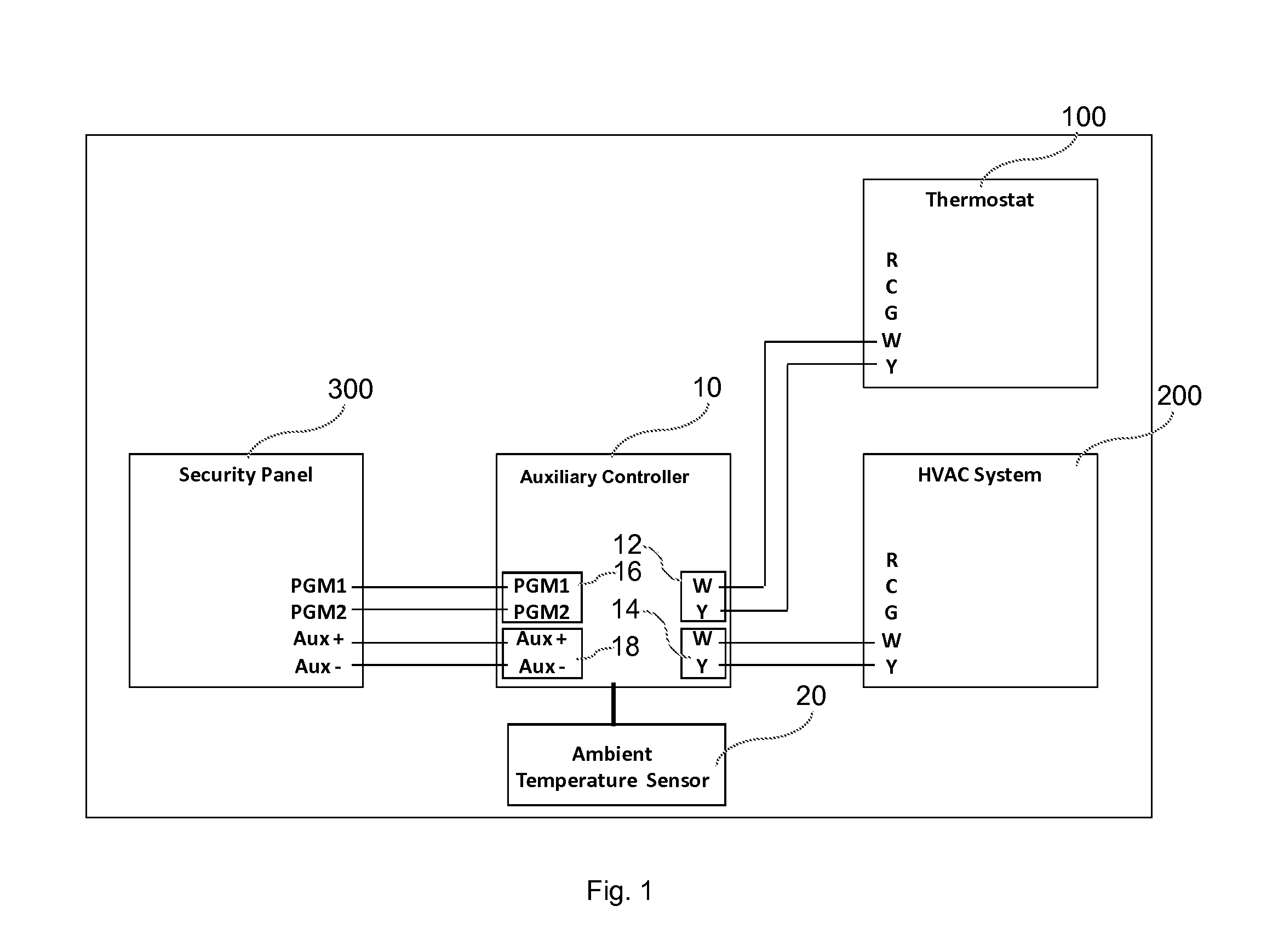
[0020]Turning now to FIG. 1, there is shown a control system 1 comprising a thermostat 2, an HVAC system 4, a security panel 6 of a security system, and an auxiliary controller 10 according to an embodiment of the invention.

[0021]The auxiliary controller 10 includes a thermostat interface 12 for receiving control signals by wire from thermostat 2, an HVAC system interface 14 for providing control signals by wire to HVAC system 4, and a security system interface 16 for receiving armed status signals by wire from the security panel 6. The auxiliary controller 10 also includes power terminals Aux + and Aux − for receiving 12 VDC power from a power source and providing the power to the components of the auxiliary controller. In this embodiment, the power terminals of the auxiliary controller 10 receive power from the Aux + and Aux − auxiliary power output terminals of the security panel 6 itself. The auxiliary controller 10 also includes an ambient temperature sensor 20, which in this e...


PUM


Abstract

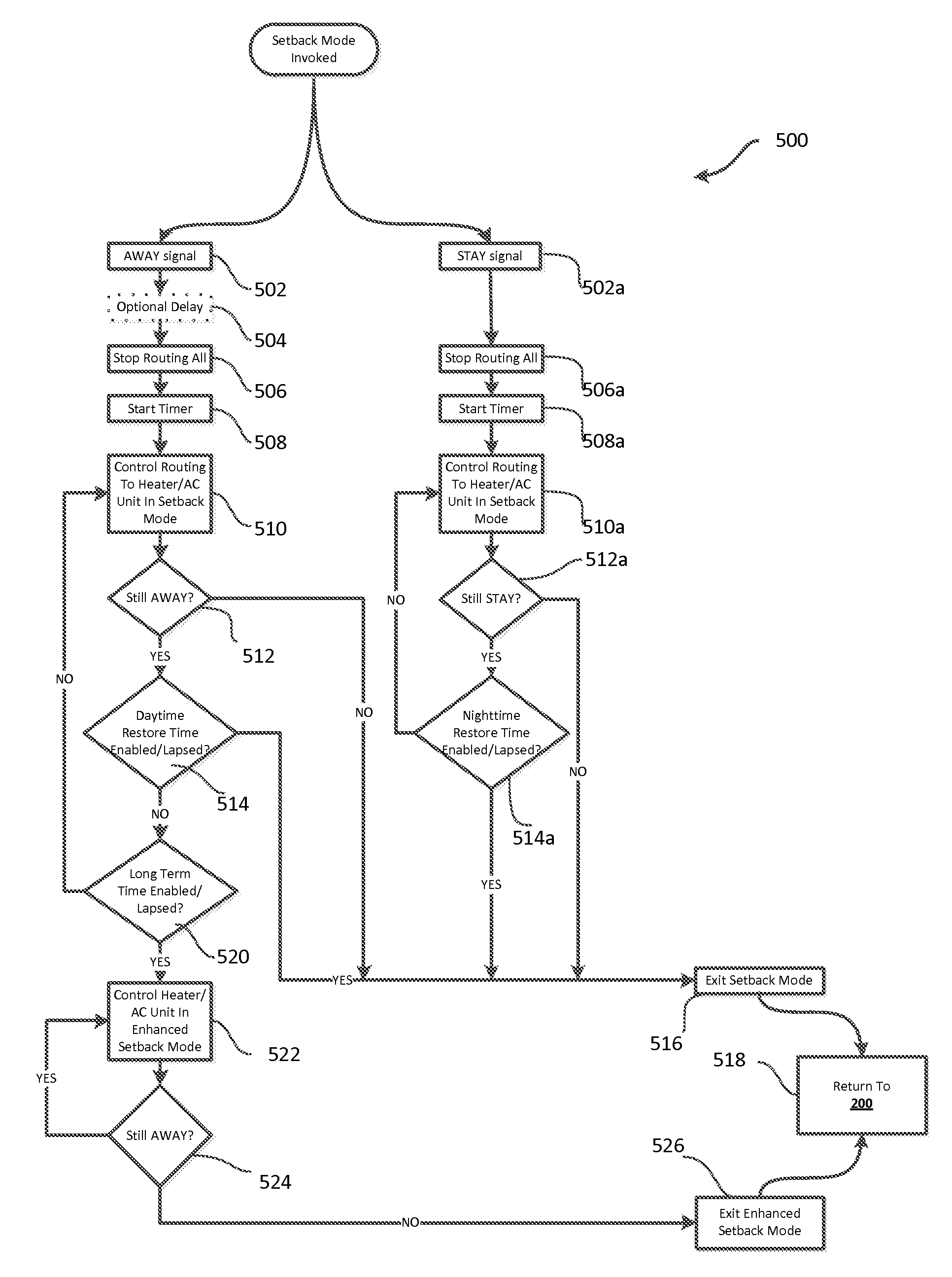
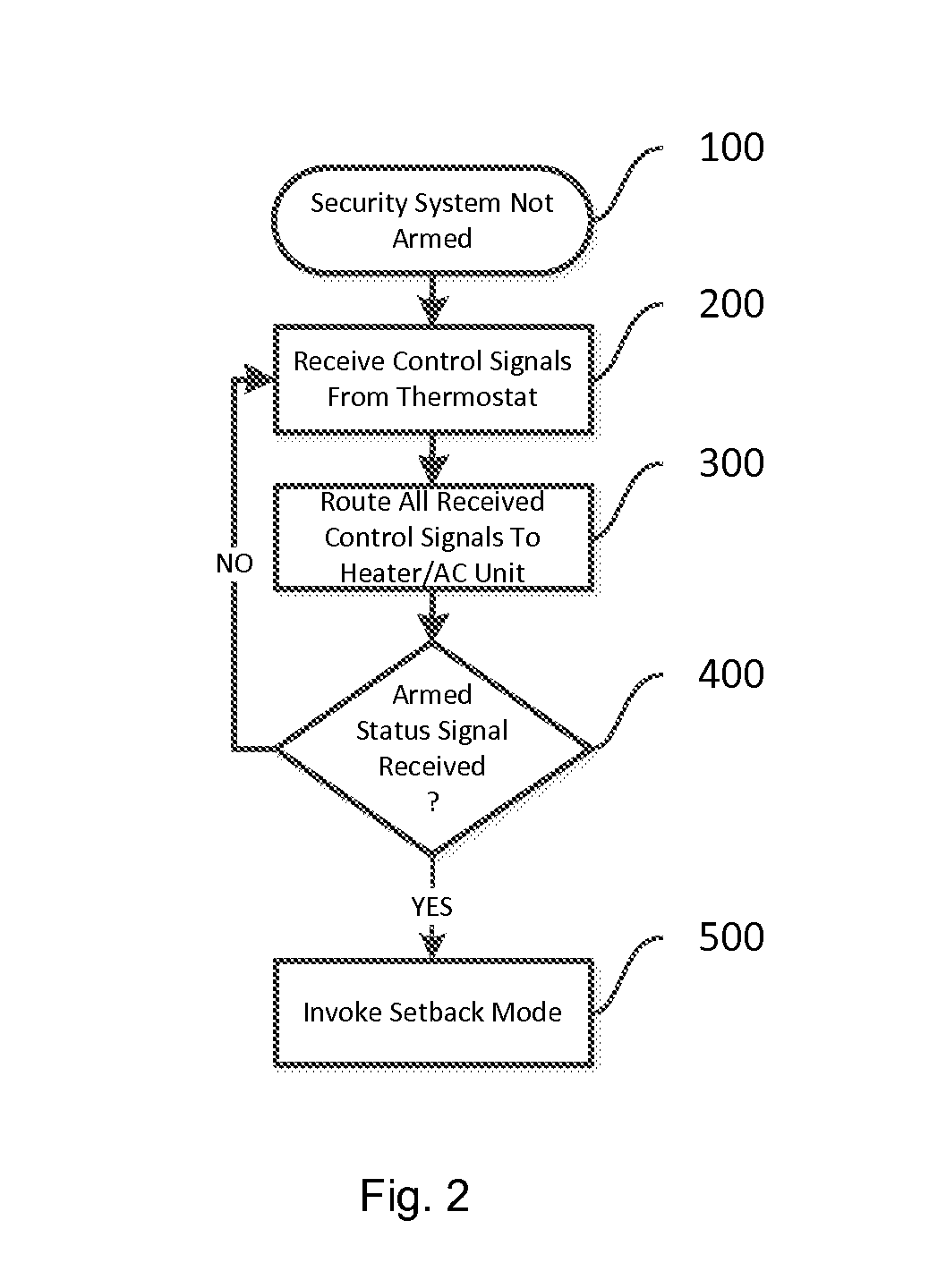
An auxiliary controller for an HVAC system includes a thermostat interface for receiving control signals by wire from a thermostat; an HVAC system interface for providing control signals by wire to an HVAC system; a security system interface for receiving armed status signals by wire from a security system; and processing structure configured to, while the security system is disarmed, permit routing of all control signals received from a thermostat to an HVAC system and, upon arming of the security system, invoke a setback mode including controlling the routing to reduce energy consumption.

Description

FIELD OF THE INVENTION[0001]The present invention relates generally to control of heating, ventilation and / or air conditioning (HVAC) systems and more particularly to an auxiliary controller for an HVAC system and a method for controlling an HVAC system.BACKGROUND OF THE INVENTION[0002]The general class of environmental control systems known as HVAC (heating, ventilation and air conditioning) systems is well known. Such systems are in common use for heating and / or cooling dwellings such as homes, office buildings, malls, hotel rooms and other interior spaces that are normally occupied by people, and for ventilating the dwellings by circulating heated, cooled or ambient air throughout the home.[0003]For example, a central heating system including a forced air furnace powered by gas, oil or electricity is very commonly incorporated into North American homes, and is typically under the control of a thermostat. The thermostat senses the ambient temperature within a space in the home and...

Claims


Application Information

Patent Timeline
IPC IPC(8): G05D23/19F24F11/02
CPCG05D23/1902G08B25/008F24F2011/0075F24F11/006F24F2011/0065F24F11/0034F24F11/30F24F2120/10F24F11/62F24F11/66F24F11/46
Inventor REMME, RANDALL
Owner REMME RANDALL
Learn More