Stator in an electric motor

a technology of electric motor and stator, which is applied in the direction of unknown materials, plant/algae/fungi/lichens ingredients, and magnetic circuit shape/form/construction, etc. it can solve the problems of damage to the connection of adjacent teeth segments, and achieve high stability, advantageous magnetic flux profile, and easy manufacturing

Inactive Publication Date: 2013-01-31
ROBERT BOSCH GMBH
View PDF1 Cites 12 Cited by
  • Summary
  • Abstract
  • Description
  • Claims
  • Application Information

AI Technical Summary

Benefits of technology

[0005]The aim underlying the invention is to specify a stator in an electric motor, which is easy to manufacture, using simple design-related mea

Problems solved by technology

The problem with such connections is basically that the connection between the tooth segments has to be able to absorb the forces occurring during operation without changing the relative positi

Method used


Image

  • Stator in an electric motor
  • Stator in an electric motor
  • Stator in an electric motor

Examples


Embodiment Construction

[0030]In the figures, identical components are provided with identical reference numerals.

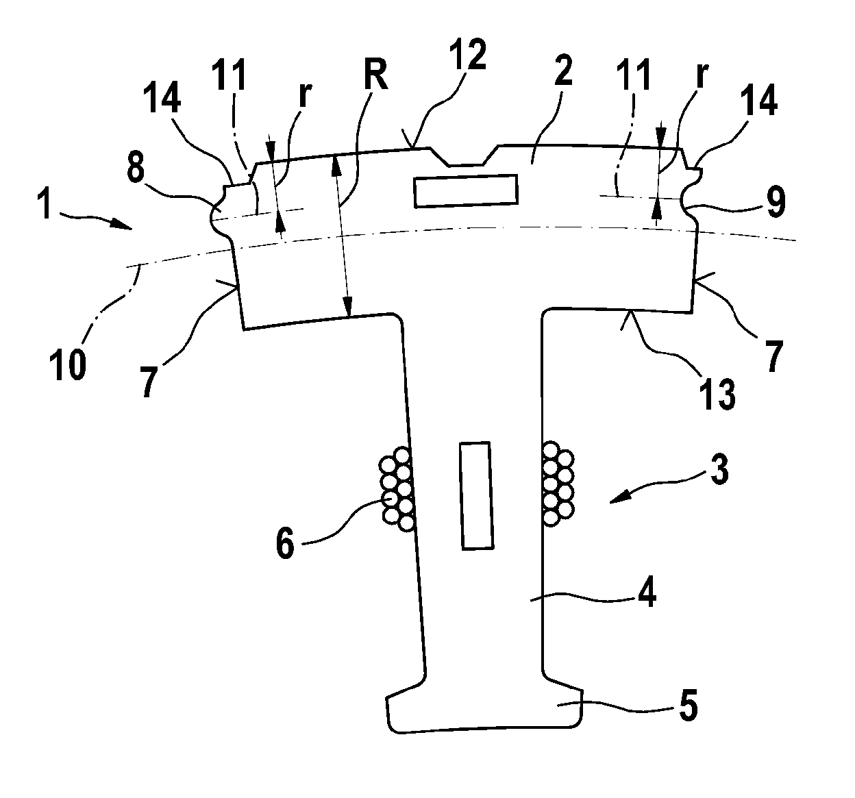
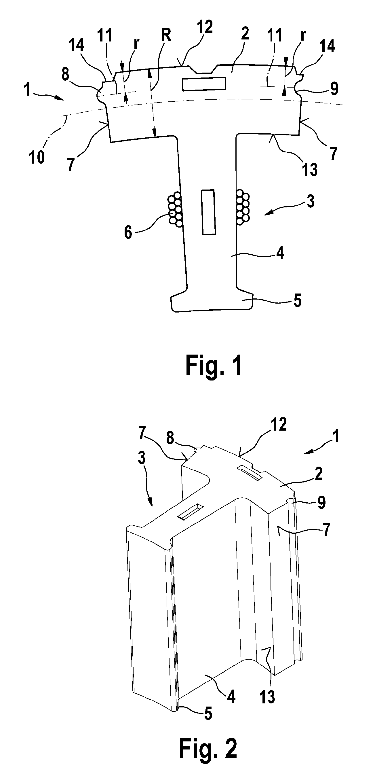
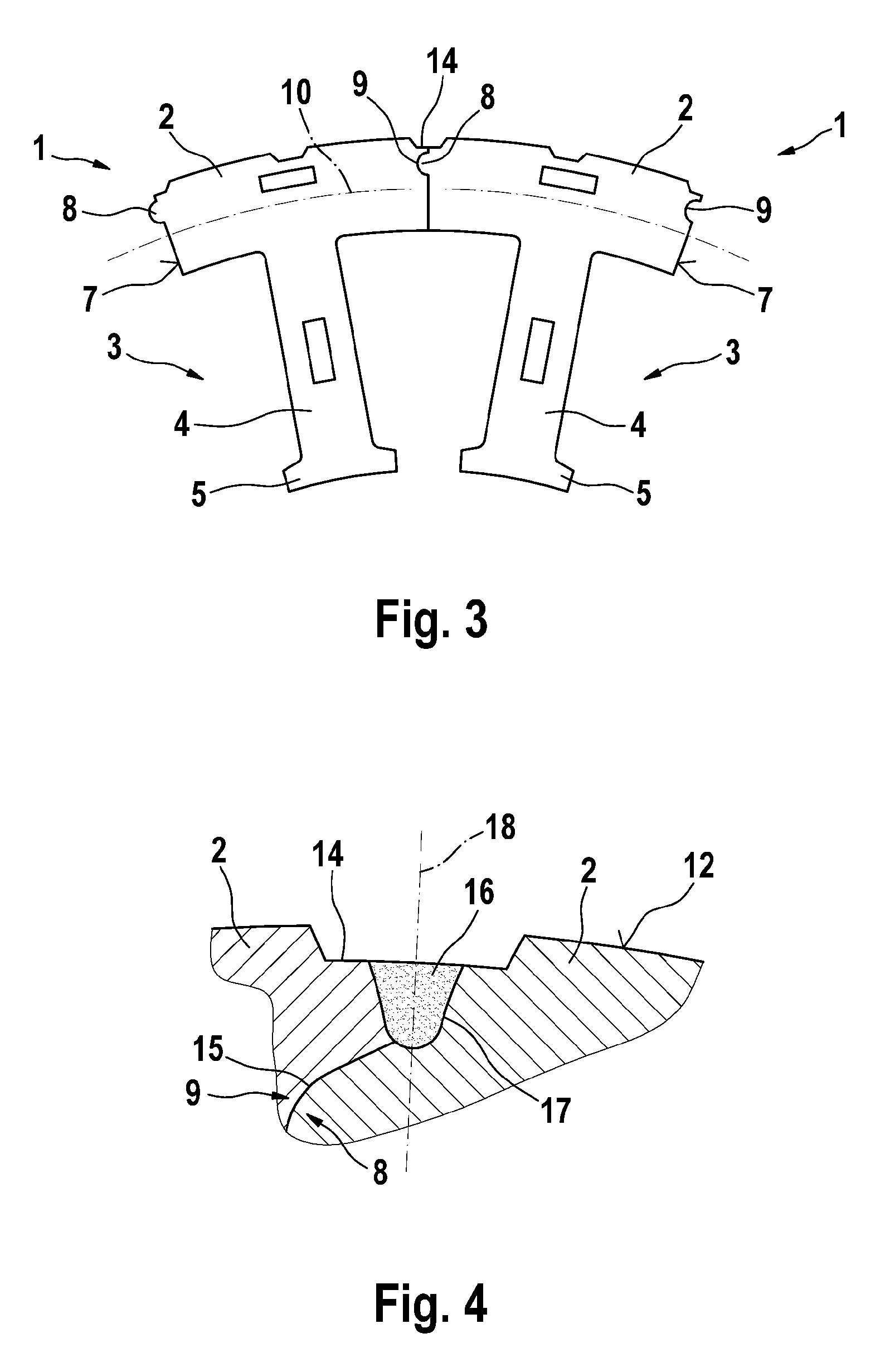
[0031]In FIGS. 1 and 2, an individual teeth segment is depicted in each case, which is a constituent part of a stator in an EC internal-rotor electric motor and can collectively compose a stator ring with similar teeth segments. The teeth segment 1 comprises a radially outer yoke segment 2 extending in the peripheral direction and a support tooth 3 which is integrally designed with the yoke segment, extends radially inwards and is the support for a coil 6 through which current can be passed. The support tooth 3 consists of a radially aligned base body 4, the coil being wound around the lateral surface thereof, and a radially inner tooth crest 5 which is widened in the peripheral direction with respect to the base body 4 and forms a pole shoe. The radially inner front side of the tooth crest 5 lies immediately adjacent to the rotor which is enclosed by the stator, wherein an annular air gap is s...


PUM


Abstract

The invention relates to a stator in an electric motor comprising a plurality of teeth segments forming a stator ring, said teeth segments comprising outer yoke segments and radial support teeth. Connection elements are arranged on the peripheral front sides of the yoke segment and are offset in the direction of the radial outer side.

Description

BACKGROUND OF THE INVENTION[0001]The invention relates to a stator in an electric motor, in particular in an actuator for a motor vehicle.[0002]EC internal-rotor motors comprising stators are known from prior art, which have a stator ring located radially on the outside and a plurality of support teeth, which are distributed evenly over the periphery and extend radially inwards, for receiving coils through which current can be passed. The stator ring is composed of individual teeth segments, which in each case consist of a return-path segment or respectively a yoke segment and a support tooth, the yoke segments forming the continuous stator ring of the stator in the assembled state. Each tooth segment is composed of stamped sheet metal sheets that are assembled in layers. Such a stator is, for example, described in the Chinese patent publication CN 101442224 A.[0003]Knob-like raised portions or recesses corresponding thereto, which in the assembled state mesh with each other in a po...

Claims


Application Information

Patent Timeline
IPC IPC(8): H02K1/18A61K35/644
CPCH02K2213/03H02K1/148A23L2/395A23L2/40A23L2/52A23L33/105A61K35/644A61K36/11A61K36/185A61K36/752A61K2300/00
Inventor FEUERROHR, LINEWERT, ANDREASGUTMANN, MARTINDEVERMANN, THOMASNOMMENSEN, BJOERN
Owner ROBERT BOSCH GMBH
Why Eureka
Try Eureka