Speaker apparatus and audio output method

a technology of speaker apparatus and audio output, which is applied in the direction of electrical transducers, transducer types, electric/electrostrictive transducers, etc., can solve the problems of dust entering the speaker system, insufficient sound output in the low pitch range, and speaker system b>1/b>, etc., to achieve enhanced sound output in the lower range, simple structure, and increased size

Inactive Publication Date: 2013-01-31
SONY CORP
View PDF4 Cites 13 Cited by
  • Summary
  • Abstract
  • Description
  • Claims
  • Application Information

AI Technical Summary

Benefits of technology

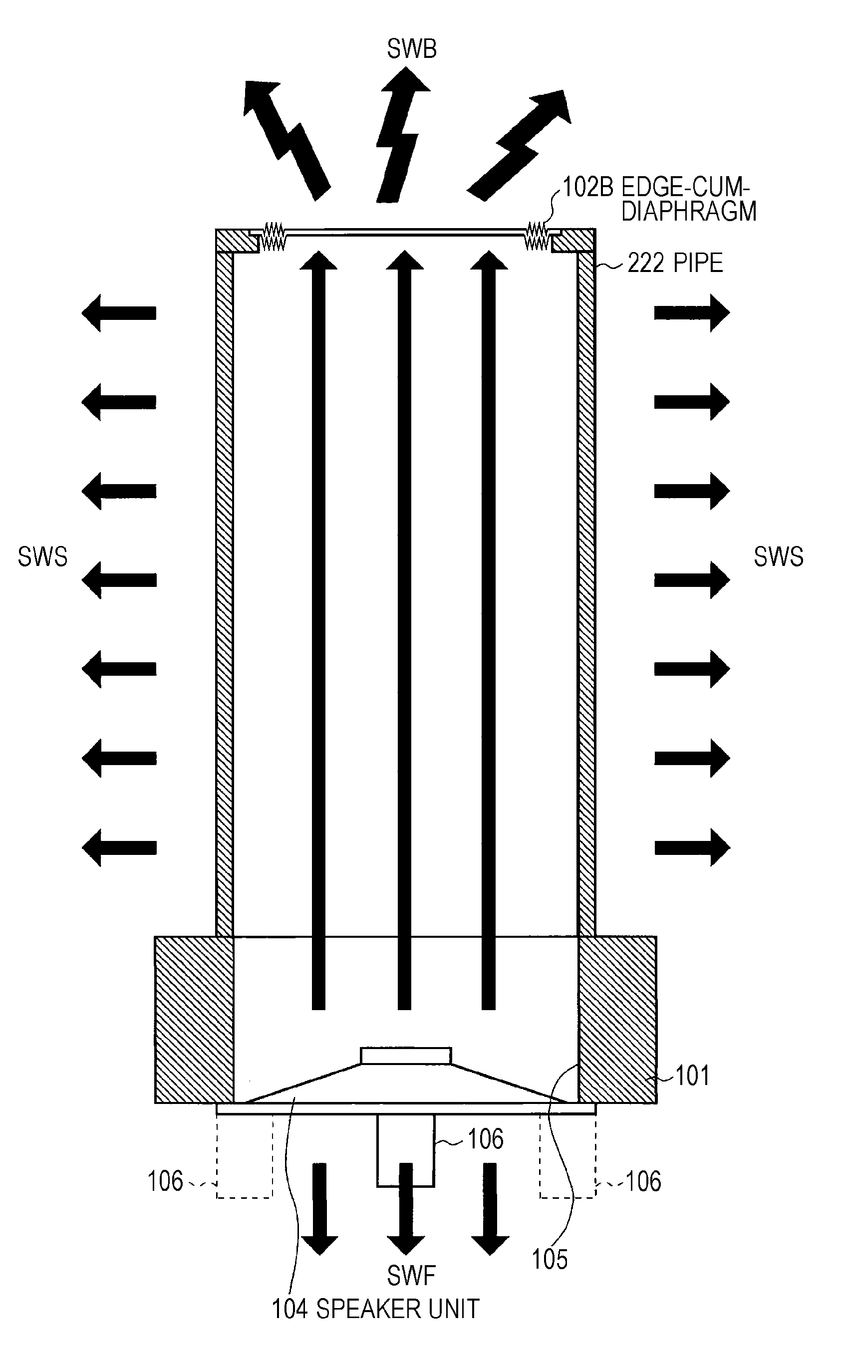
[0018]According to the present invention, the cylindrical member functions as the resonance tube by being excited to vibration with the sound wave passing through the cylindrical member, and the diaphragm functions as the passive radiator in response to the sound wave passing through the cylindrical member, thereby allowing the output of sound in the lower range to be further enhanced than heretofor

Problems solved by technology

Now, the speaker system 1 described in Patent Document 1 has had a problem of insufficient output of sound in a low pitch range due to a structure that the regular speaker unit alone is in charge of the lower ra

Method used


Image

  • Speaker apparatus and audio output method
  • Speaker apparatus and audio output method
  • Speaker apparatus and audio output method

Examples


embodiment

1. Embodiment

[1-1. Structure of a Speaker Apparatus]

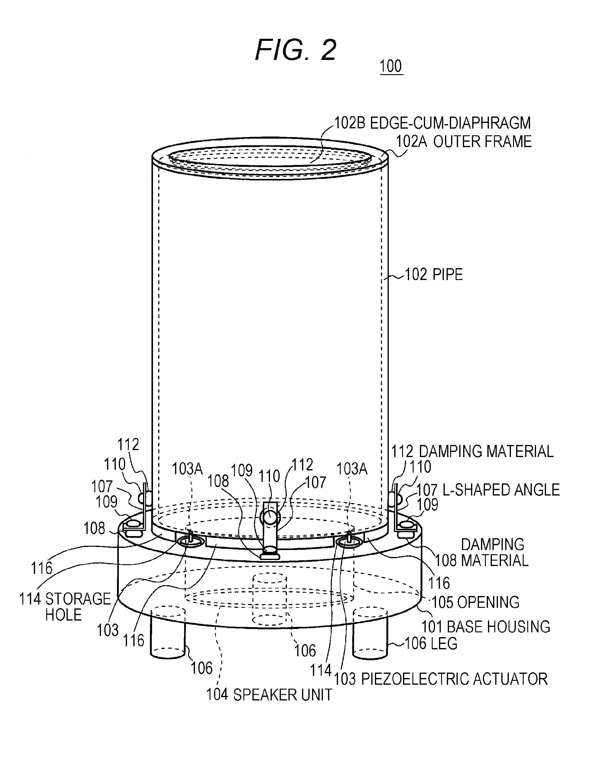
[0045]As shown in FIGS. 2 to 5, a speaker apparatus 100 includes a base housing 101, a pipe 102, a piezoelectric actuator 103, and a speaker unit 104 using an electric actuator (not shown) as a sounding body.

[0046]The base housing 101 is formed of a synthetic resin, for example, and is formed into a disk shape, a center part of which is provided with an opening 105 penetrating through the base housing in a cylindrical shape. The base housing 101 is also provided with three legs 106 planted at equal intervals along an outer circumference side of a bottom surface of the base housing, for example.

[0047]The base housing 101 can achieve stable installation by including three legs 106 as compared to four legs, for example, since these three legs 106 would be surely brought into contact with an installation surface.

[0048]Furthermore, the bottom surface of the base housing 101 can be separated from the installation surface by the legs 106 ...


PUM


Abstract

The present invention allows for the further enhancement of a low pitch range with a simple structure without increasing the size. The present invention is provided with: a pipe (102) open one end side and the other end side; a speaker unit (104) that is coaxial with the pipe (102), arranged at the one end side of the pipe (102), and driven on the basis of an audio signal; and an edge-cum-diaphragm (102B) that is coaxial with the pipe (102), installed at the other end side of the pipe (102), and vibrates in response to a sound wave that passes through the pipe (102). While the pipe (102) functions as a resonance tube by being excited to vibration with the sound wave that is radiated from the speaker unit (104) and passes through the pipe (102), the edge-cum-diaphragm (102B) functions as a passive radiator by vibrating in response to the sound wave that passes through the pipe (102).

Description

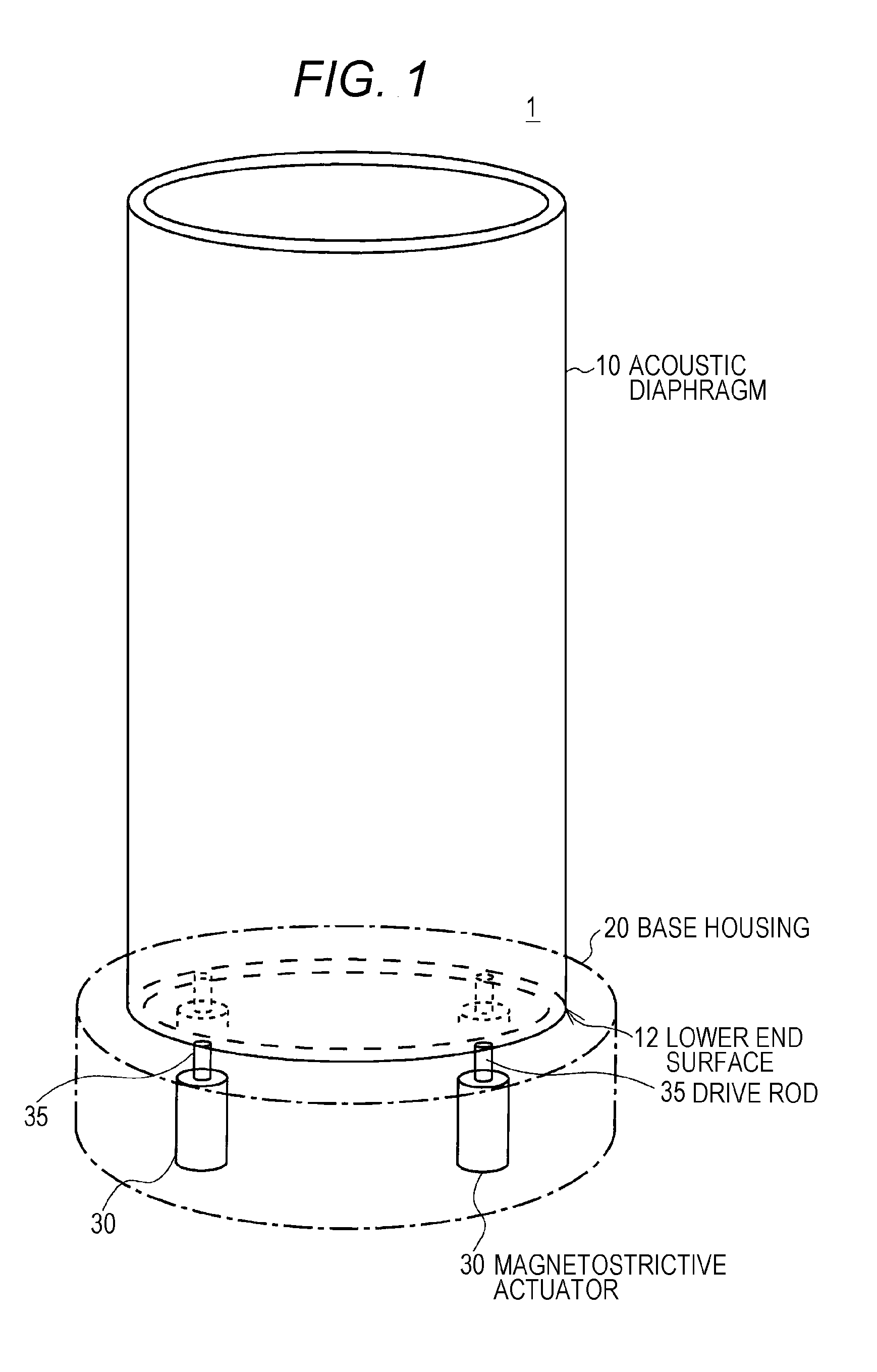
TECHNICAL FIELD[0001]The present invention relates to a speaker apparatus and an audio output method, and is preferable for application in obtaining an audio image with a sense of spread by exciting a pipe wall of a cylindrical member with a sound wave from a sounding body that is driven on the basis of an audio signal and radiating the sound wave outward from the entire outer surface of the cylindrical member.BACKGROUND ART[0002]Conventionally, there has been proposed a speaker system that reproduces sound by adding vibration to an acoustic diaphragm by a magnetostrictive actuator (refer to Patent Document 1, for example).[0003]In a speaker system 1, as shown in FIG. 1, a cylindrical acoustic diaphragm 10 formed of an acrylic resin or the like is vertically supported on a discoid base housing 20, and four magnetostrictive actuators 30 are arranged at equiangular intervals in the base housing 20.[0004]In the speaker system 1, a drive rod 35 for each magnetostrictive actuator 30 abut...

Claims


Application Information

Patent Timeline
IPC IPC(8): H04R1/28
CPCH04R1/02H04R1/2834H04R5/02H04S5/00H04R2205/022H04R2217/01H04R17/00
Inventor SUZUKI, NOBUKAZUOHASHI, YOSHIO
Owner SONY CORP
Why Eureka
Try Eureka