

Lead storage battery
a lead storage battery and lead technology, applied in the field of electrochemistry, can solve the problems of weak current pulse generators that are not satisfactory in preventing deterioration and sulfate film removal devices, and achieve the effect of reducing size and cost, size and weight, and remarkably reducing the size and cos
- Summary
- Abstract
- Description
- Claims
- Application Information
AI Technical Summary
Benefits of technology
Problems solved by technology
Method used
Image

Examples
example 1
[0038]An open-type lead storage battery 55-24L that had been mounted on a vehicle for four years was regenerated and subjected to a test.
[0039]A voltage at the starting time was 13.2 V, and capacity in a 10 A discharge test was 32 Ah.
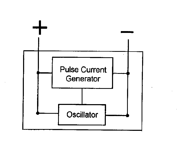
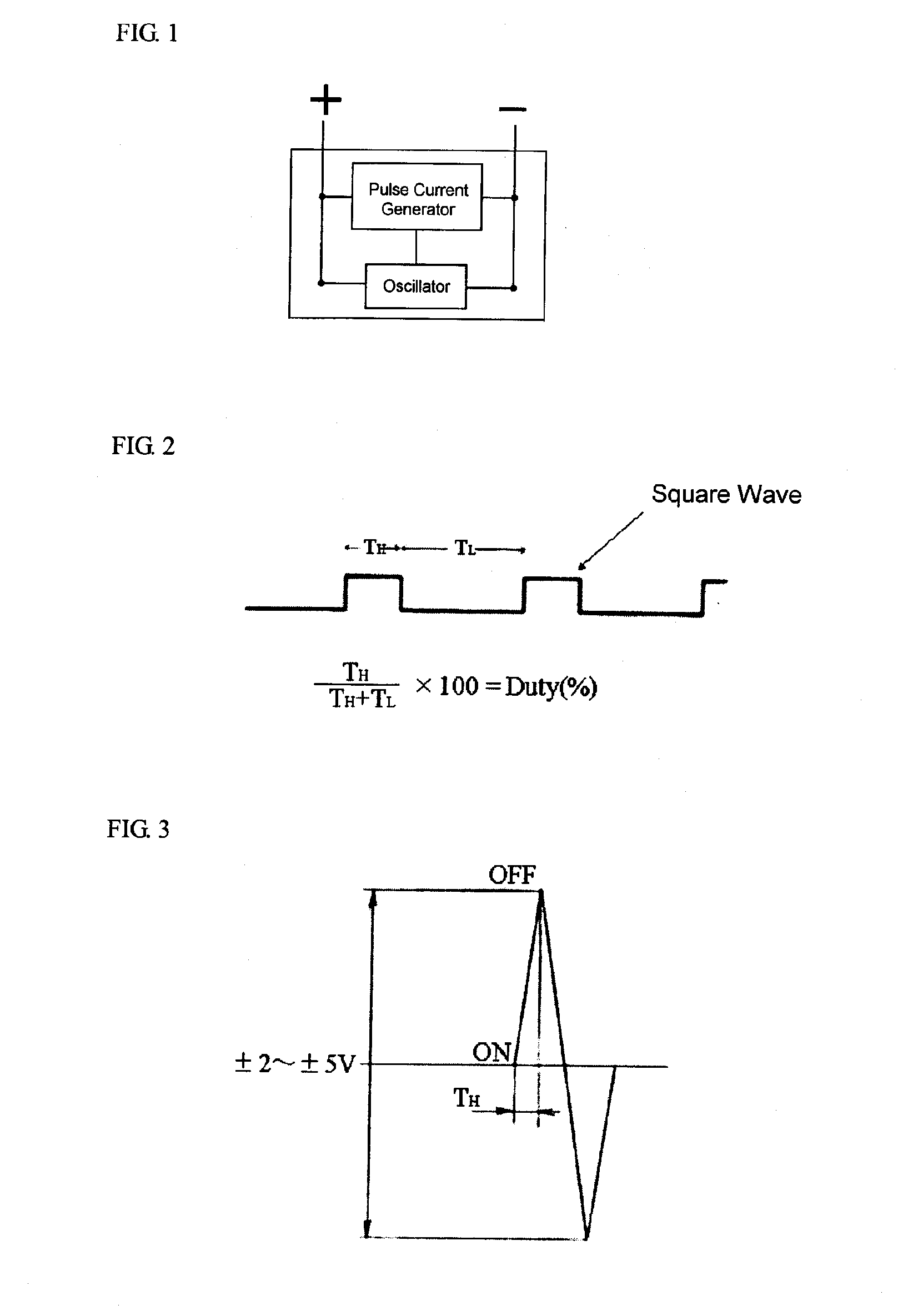
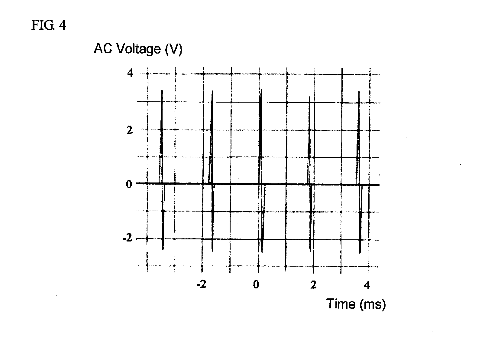
[0040]To this lead storage battery, high-density polyoxyethylene distyrenated phenyl ether was added so that 1CC (1.2% by weight with respect to the electrolytic solution) was added to each cell. A lead sulfate film removing device shown in FIG. 1, which applies a weak pulse current (number of pulses: 5400 times per second, AC pulse voltage of the applied current: +3.4 V, −2.4 V) of a waveform shown in FIG. 4, was installed.
[0041]After two years had passed and after about 100,000 km of driving, a voltage was 13.1 V and the capacity of 10 A discharge test was 32 Ah.
[0042]Even when two years had passed, no deterioration phenomena were recognized, it was demonstrated that addition of a nonionic dispersing agent to a lead storage battery and use together wi...
PUM
| Property | Measurement | Unit |
|---|---|---|
| voltage | aaaaa | aaaaa |
| voltage amplitude | aaaaa | aaaaa |
| temperature | aaaaa | aaaaa |
Abstract
Description
Claims
Application Information