Electrical contacts for vacuum circuit breakers and methods of manufacturing the same

a technology of electrical contacts and vacuum circuit breakers, which is applied in the direction of contact, air break switch, high-tension/heavy-dress switch, etc., can solve the problems of low surge voltage, increase in size and cost of electrical equipment, and electrical equipment insulation breakage, etc., to reduce size, interrupt a large current, and excellent interruption performance

Inactive Publication Date: 2010-02-16
HITACHI LTD
View PDF14 Cites 10 Cited by
  • Summary
  • Abstract
  • Description
  • Claims
  • Application Information

AI Technical Summary

Benefits of technology

[0012]An object of the present invention is to provide an electrical contact having excellent interruption performance and showing a low surge voltage concurrently, showing less deterioration in performances even after multi-time interruption, that can yield, for example, a vacuum circuit breaker, which is reduced in size and cost, and a method for manufacturing the electrical contact.
[0017]The configuration provides a vacuum circuit breaker that has a reduced size and can interrupt a large current. It can also provides a vacuum circuit breaker that has excellent interruption performance and shows a low surge voltage concurrently.
[0018]The present invention can provide electrical contacts that combine excellent interruption performance and low-surge performance and show less deterioration in performances even after multi-time interruption.

Problems solved by technology

If current of the vacuum interrupter used in an inductive circuit is interrupted, abnormal surge voltage is induced, which may lead to insulation breakage of electrical equipment.
Accordingly, they must use a surge absorber for absorbing the abnormal surge voltage, and this leads to increase in size and cost of electrical equipment.
The vacuum circuit breakers typically using Co—Ag—Se alloy electrical contacts show a low surge voltage but are unsuitable for large-current interruption.
The interruption performance and the low-surge property are considered to be theoretically incompatible with each other, because the current is interrupted at a higher value than zero to yield a larger chopping current with an increasing interruption performance.
In addition, the vacuum circuit breakers must maintain required properties even after carrying out interruption many times, but electrical contacts combining excellent large-current interruption performance and low-surge performance may have reduced low-surge performance after carrying out interruption many times.

Method used


Image

  • Electrical contacts for vacuum circuit breakers and methods of manufacturing the same
  • Electrical contacts for vacuum circuit breakers and methods of manufacturing the same
  • Electrical contacts for vacuum circuit breakers and methods of manufacturing the same

Examples


embodiment 1

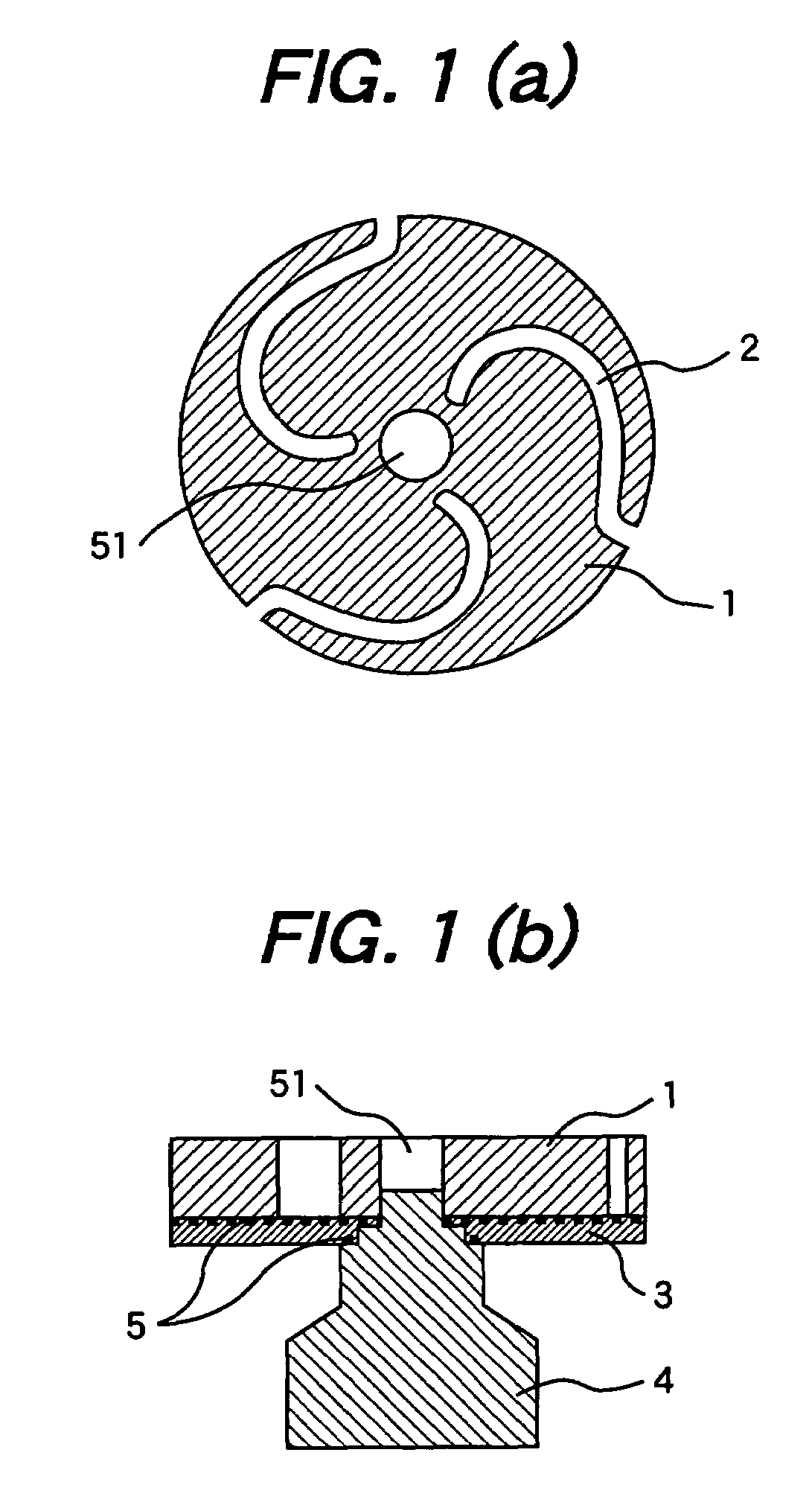
[0045]An electrical contact comprising copper as a matrix, and chromium particles surrounded by Sic and dispersed in the matrix was prepared, and an electrode was prepared using the electrical contact. FIG. 1 is a view of the prepared electrode. The electrode in FIG. 1 comprises an electrical contact 1 having spiral grooves 2 for giving driving force to arc, thereby to prevent the arc from stopping, a reinforcement plate 3 made of stainless steel, an electrode rod 4, a solder material 5, and a central hole 51 constituting a concave portion for preventing arc from generating at the center of the electrode.

[0046]The electrical contact 1 was prepared in the following manner. Initially, chromium powder and copper powder each having a average particle size of 75 μm or less, and SiC powder having a average particle size of 2 to 3 μm were mixed in a twin-cylinder mixer to make compositions of the electrical contacts shown in Table 1 below. Next, the powder mixture was charged into a die ha...

embodiment 2

[0049]In the second embodiment, electrical contacts structurally having a copper matrix and SiC particles dispersed in the matrix were prepared, and electrodes were prepared using these electrical contacts. The structure of the electrodes is the same as in the first embodiment, as shown in FIG. 1.

[0050]The electrical contact 1 was prepared in the following manner. Initially, chromium powder, SiC powder and the balance being cu each having a average particle size of 75 μm or less were mixed in a twin-cylinder mixer to make compositions of the electrical contacts shown in Table 1 below. Next, the powder mixture was charged into a die having such a shape as to form the through spiral grooves 2 and central hole 51 and yield the desired shape of the electrical contact, and the charged mixture was subjected to compact molding under a hydraulic pressure of 400 MPa. The density of the resulting compacted molding was about 73%. This was sintered at 900° C. to 1050° C. in a vacuum for two hou...

embodiment 3

[0056]Using the electrodes manufactured in the first and second embodiments, a vacuum interrupter provided with the electrode was manufactured. The specification of the vacuum interrupter were: a rated voltage of 7.2 kV, a rated current of 600 A, and a rated interrupting current of 20 kA.

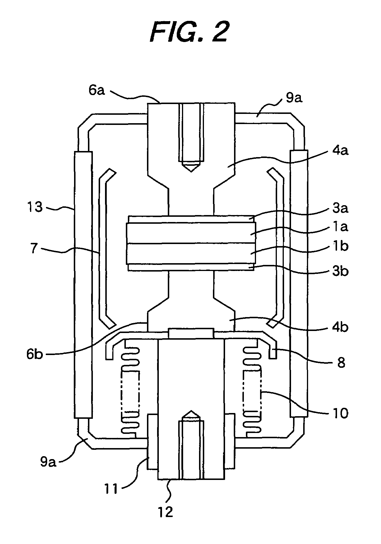
[0057]FIG. 2 is a view showing the structure of the vacuum interrupter according to the third embodiment. The vacuum interrupter in FIG. 2 comprises a fixed electrical contact 1a, a movable electrical contact 1b, reinforcement plates 3a and 3b, a fixed electrode rod 4a and a movable electrode rod 4b, so that the fixed electrode 6a and the movable electrode 6b are constituted.

[0058]The movable electrode 6b is bonded by soldering to a movable holder 12 through a movable shield 8 for preventing scattering of metal vapor upon current interruption. These members are highly vacuum-tightly sealed by soldering with a fixed end plate 9a, a movable end plate 9b, and an insulating cylinder 13. The screw portio...


PUM

PropertyMeasurementUnit
decomposition pointaaaaaaaaaa
interrupting currentaaaaaaaaaa
particle sizeaaaaaaaaaa

Abstract

An electrical contact used herein comprises chromium; one of copper and silver; and a carbide, in which the electrical contact comprises a matrix and chromium, the matrix phase mainly comprising one of copper and silver, and the chromium being surrounded by the carbide and dispersed in the matrix. The electrical contact contains 1 to 30 percent by weight of a carbide, with the balance being copper. Another electrical contact contains chromium, copper, and a carbide and has a weight ratio of chromium to the carbide within the range of 1:1.5 to 1:50.

Description

CLAIM OF PRIORITY[0001]The present application claims priority from Japanese applications Serial No. 2005-198210, filed on Jul. 7, 2005 and Serial No. 2005-240546, filed on Aug. 23, 2005, the contents of which are hereby incorporated by reference into this application.FIELD OF THE INVENTION[0002]The present invention relates to a novel electrical contact for a vacuum interrupter for use typically in vacuum circuit breakers and vacuum switchgears, and a method of manufacturing the same.BACKGROUND OF THE INVENTION[0003]Vacuum interrupters disposed typically in vacuum circuit breakers and vacuum switchgears each have a pair of electrical contacts capable of being turned on and off. Receiving and distributing equipment such as vacuum circuit breakers must be downsized. To reduce such vacuum interrupters in diameter and size, the interruption performance of electrical contacts of the vacuum interrupters must be improved so as to interrupt a heavy current at electrical contacts with a sma...

Claims


Application Information

Patent Timeline
Patent Type & Authority Patents(United States)
IPC IPC(8): C22C5/06C22C9/00H01H33/66
CPCH01H1/0233
Inventor KIKUCHI, SHIGERUMORITA, AYUMUKOBAYASHI, MASATOKAJIWARA, SATORUBABA, NOBORU
Owner HITACHI LTD
Why Eureka
Try Eureka