Control apparatus and control method for robot arm, robot, control program for robot arm, and integrated electronic circuit

Active Publication Date: 2013-01-31
PANASONIC CORP
View PDF0 Cites 28 Cited by
  • Summary
  • Abstract
  • Description
  • Claims
  • Application Information

AI Technical Summary

Benefits of technology

[0029]a fixing portion including a fixing member shiftable between a fixed position where the fixing member is in contact with the end effector and the grip portion to fix the end effector and the grip portion and restrict relative shift between the end effector and the grip portion, and an accommodated posi

Problems solved by technology

Patent Literature 1 has a problem in operability because the robot arm, which is attached to the distal end of the arm tip by means of the spring, is influenced by elastic force of the spring.
In addition, because the first and second robot arms do not operate in cooperation with each other, it is necessary to move the second arm after the motion of the first robot arm is completed if the task has a large working area, which leads to increase in operation steps.
In the technique according to Patent Literature 2, the retainer member can move only in the horizo

Method used


Image

  • Control apparatus and control method for robot arm, robot, control program for robot arm, and integrated electronic circuit
  • Control apparatus and control method for robot arm, robot, control program for robot arm, and integrated electronic circuit
  • Control apparatus and control method for robot arm, robot, control program for robot arm, and integrated electronic circuit

Examples


Example

First Embodiment

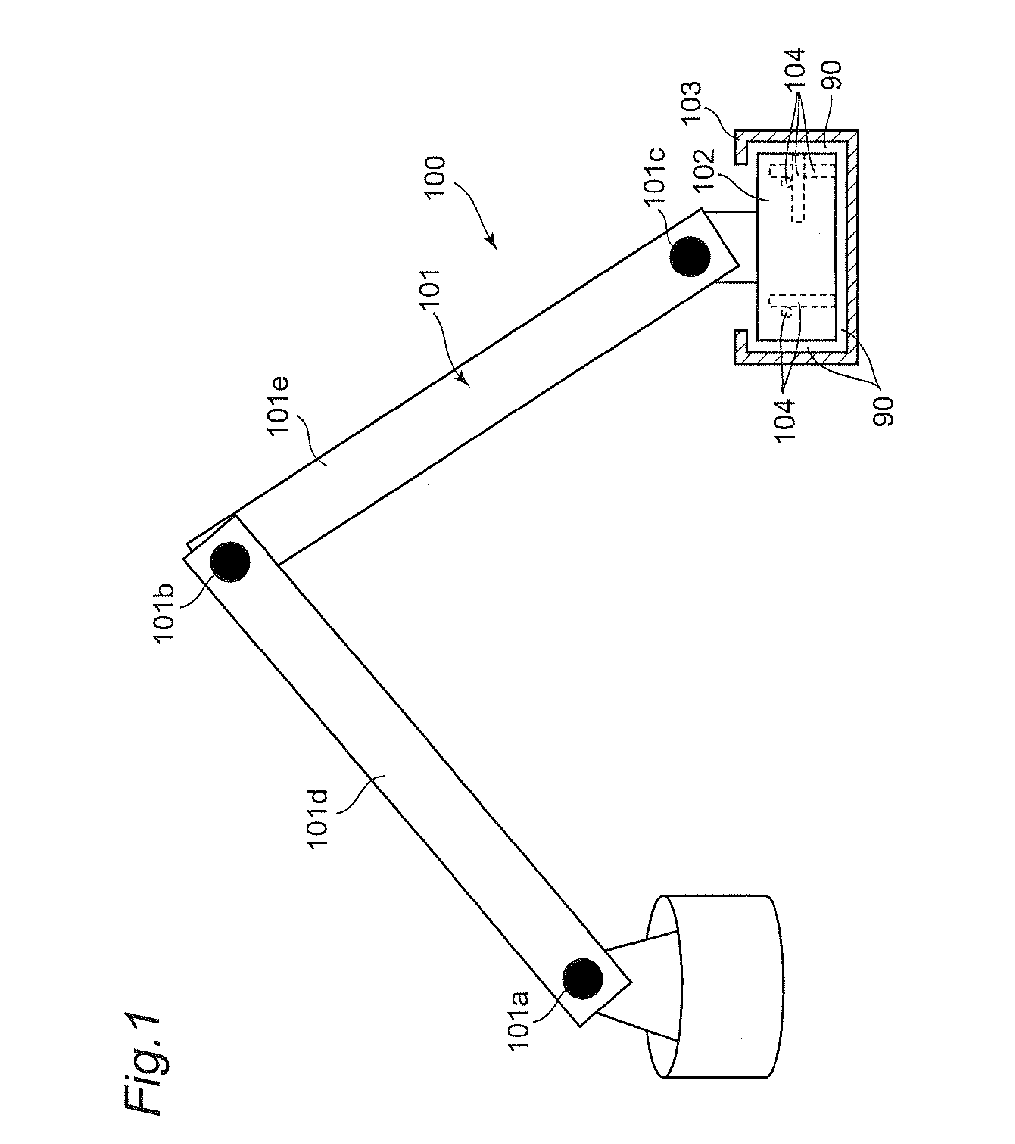
[0182]FIG. 1 shows a robot 601 including a robot arm 100, according to a first embodiment of the present invention. The robot arm 100 includes a manipulator 101 as one example of a main body of the robot arm 100, an end effector 102, a grip portion 103, and relative position sensors 104. In the present embodiment, the robot 601 is configured by the robot arm 100 and a control apparatus 602 for the robot arm.

[0183]The manipulator 101 has a plurality of multijoint mechanisms, and respective links 101d and 101e are driven to rotate about a plurality of joint shafts (101a, 101b, and 101c). The manipulator 101 has an arm tip to which an end effector 102 is attached.

[0184]The end effector 102 incorporates the plurality of relative position sensors 104, which function to measure a relative position of the grip portion 103 with respect to the end effector 102 (that is, relative positional information, in other words, measurement values or gauged values). The end effector 102...

Example

Second Embodiment

[0233]FIG. 10A is a plan view showing an end effector 102 in a rectangular parallelepiped shape having a square plane, a grip portion 103 in a quadrilateral box shape, relative position sensors 104, and four fixing portions 1001 in a robot arm 100 of a robot according to a second embodiment of the present invention. FIG. 10B is a sectional view showing the end effector 102, the grip portion 103, the relative position sensors 104, and the fixing portions 1001. This sectional view is taken along line A-A indicated in FIG. 10A and seen in the direction indicated by an arrow 10B. FIG. 10C is a sectional view showing the end effector 102, the grip portion 103, the relative position sensors 104, and the fixing portions 1001. This sectional view is taken along line B-B indicated in FIG. 10A and seen in the direction indicated by an arrow 10C. In the robot according to the second embodiment of the present invention, the end effector 102, the grip portion 103, and the relati...

Example

Third Embodiment

[0278]In the second embodiment, the fixing switch unit 1202 switches between the “fixing” state and the “not fixing” state during the teaching motion and the playback motion, respectively. However, in such a configuration, there may arise a problem that the movable range in the “fixing” state during the teaching motion differs from the movable range in the “not fixing” state during the playback motion. A robot according to a third embodiment of the present invention has a solution to such a problem. The difference of the movable ranges mentioned above are detailed with reference to (a)-(c) of FIG. 18.

[0279]The views (a)-(c) of FIG. 18 show the manipulator 101 and a movable range of the manipulator 101 in the y axis direction (see FIG. 7). The region surrounded by a dotted line corresponds to a movable region 80 of the manipulator 101. The movable region 80 means a region where the manipulator 101 is operable.

[0280]Firstly, the view (a) of FIG. 18 shows the state wher...


PUM


Abstract

There is provided a control apparatus and control method for robot arm, robot, control program for robot arm, and integrated electronic circuit, which can improve robot arm operability upon performing tasks such as cooperative conveyance and direct teaching. The grip portion separated from the end effector attached to the robot arm is provided. When a person grips and shifts the grip portion, a tracking control unit controls so that the robot arm follows the shift. A fixing switch unit switches between a fixing state where, upon switching to “playback mode”, a fixing portion is located at a fixed position to fix the end effector and the grip portion to maintain a gap distance therebetween and a relatively shiftable state where, upon switching to “teaching mode”, the fixing portion is located at an accommodated position to relatively shift them from each other without maintaining the gap distance.

Description

[0001]This is a continuation application of International Application No. PCT / JP2012 / 000034, with an international filing date of Jan. 5, 2012, which claims priority of Japanese Patent Application No. 2011-015226 filed on Jan. 27, 2011, the content of which is incorporated herein by reference.TECHNICAL FIELD[0002]The technical field relates to a control apparatus and control method for a robot arm, a robot including the control apparatus for a robot arm, a control program for a robot arm, and an integrated electronic circuit, which are used for causing motions of the robot to perform desired tasks such as teaching or cooperative conveyance.BACKGROUND ART[0003]In recent years, model changes at manufacturing sites have been frequently observed in order to realize small lot production in great varieties. In such recent manufacturing sites where cell production has been widely conducted, in order to automate, with use of robots, thread fastening, fitting and attaching components, insert...

Claims


Application Information

Patent Timeline
IPC IPC(8): G06F19/00
CPCG05B19/423Y10T74/20305G05B2219/39209G05B2219/36453Y02P90/02
Inventor FUDABA, YUDAIYAMAMOTO, MASAKITSUSAKA, YUKOSATO, TAICHI
Owner PANASONIC CORP
Why Eureka
Try Eureka