Method and device for sealing a joint gap

a joint gap and sealing technology, applied in the direction of sealing apparatus, machines/engines, manufacturing tools, etc., can solve the problems of not being able to penetrate into the gap between the sheets, significant material saving and thus also cost and weight, and non-thixotropic polymer materials in the form of applied pastes or the like are not or only very difficult to dose and process, so as to prevent corrosion of the joint gap, good adhesion of the applied polymer particles, and effective sealing

Inactive Publication Date: 2019-07-04
RAANTEC
View PDF0 Cites 0 Cited by
  • Summary
  • Abstract
  • Description
  • Claims
  • Application Information

AI Technical Summary

Benefits of technology

[0008]In accordance with the invention, a plasma jet is used to deposit polymer particles on the joined elements from which the joint gap seal is formed. The polymer powder introduced into the plasma jet assumes a dough-like consistency in the plasma jet, which leads to good adhesion of the applied polymer particles to the joined elements in the area of the joint gap. In connection with the preheating of the area to which the doughy polymer particles are applied, the energy input of the plasma beam in this area leads to a melting of the deposited polymer particles, which creates a melt bath or a melting bead during a feed between the plasma and polymer jets and the joined elements. In the melt bath or bead, the deposited polymer takes on a consistency that fills the joint gap. The result is a joint gap seal which penetrates into the joint gap and prevents corrosion of the joint gap from the inside.
[0044]The shape and size of the melting bead can also be monitored in one embodiment of the method, e.g., with the aid of automatically evaluated camera images, wherein the process parameters are adapted in such a way that a desired shape and / or size of the melting bead is maintained. In this way, deviations in the thickness of the sheets 1, 2 or the joint gap 5 and / or an increased material consumption of the polymer powder can be automatically compensated for by penetration of the joint gap 5 at different depths.

Problems solved by technology

Such a joint gap seal seals the two sheets in the transition area superficially, but is not able to penetrate into a gap between the sheets due to its consistency.
The accumulated can lead to corrosion over time despite a possible coating of the sheets.
This leads to a significant saving in material and thus also in costs and weight compared to a sealing essentially arranged on the outside of the joint gap in accordance with the prior art.
However, precisely such non-thixotropic polymer materials in the form of applied pastes or the like are not or only very difficult to dose and process, as they pull threads, for example.

Method used


Image

  • Method and device for sealing a joint gap
  • Method and device for sealing a joint gap

Examples


Embodiment Construction

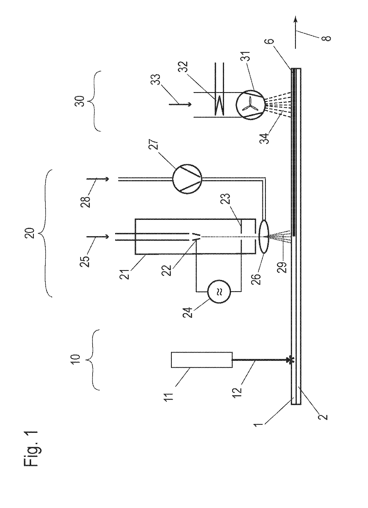
[0022]FIG. 1 schematically illustrates an exemplary embodiment of a device for applying a joint gap seal. The figure shows the device in a side view, wherein some elements are shown in sectional views to illustrate their internal structure.

[0023]The device processes a joined arrangement of at least two sheets lying on top of each other, a first sheet 1 and a second sheet 2 arranged on top of it. For this purpose, the arrangement of the two sheets 1, 2 moves relative to the device as indicated by a movement arrow 8. The movement arrow 8 indicates a feed direction of the arrangement of the two sheets 1, 2 relative to the device. In an alternative configuration, the device can be moved instead of the arrangement.

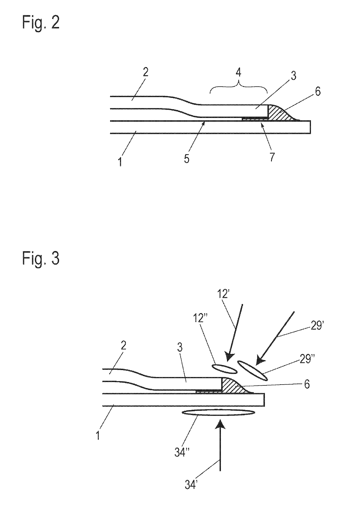
[0024]The arrangement of sheets 1, 2 processed by the device is illustrated in an example in a sectional drawing in FIG. 2. The section is executed in a plane perpendicular to the display plane of FIG. 1. It shows the first sheet 1, which is the lower one in FIG. 2, on which th...


PUM

PropertyMeasurementUnit
particle sizeaaaaaaaaaa
diameteraaaaaaaaaa
temperatureaaaaaaaaaa

Abstract

A method for sealing a joint gap between mutually joined elements, at least one of which is a sheet, by applying a joint gap seal involves preheating an area of the joined elements to which the joint gap seal is to be applied. A polymer powder is introduced into a plasma jet to form a plasma and powder jet directed towards the preheated region of the elements. Polymer particles melted in the plasma and powder jet are deposited as joint gap seal.

Description

BACKGROUND AND SUMMARY OF THE INVENTION[0001]Exemplary embodiments of the invention relate to a method and a device for sealing a joint gap between mutually joined elements, at least one of which is a sheet metal, by applying a joint gap seal.[0002]Particularly in body construction in the automotive industry, there is a need to seal mutually joined elements, e.g., two joined sheets, in the joint area and thus to seal them. Doors, flaps or other car body elements with a cavity are usually made of two or more sheet metal elements formed in a stamping and embossing process. The sheet metal elements are usually laid one on top of the other so as to surround each other and are joined together along their overlap area. A joint connection can, for example, be made via a weld seam, via an arrangement of welding points or via an adhesive joint.[0003]The joint area is often formed in the manner of a seam, i.e., the edges of two sheets do not lie on top of each other, but one of the sheets lie...

Claims


Application Information

Patent Timeline
Patent Type & Authority Applications(United States)
IPC IPC(8): F16J15/14F16J15/10
CPCF16J15/14F16J15/102F16J15/104B05D1/10B05D3/0413B05D7/14B05D3/0218C23C4/04C23C24/10F16B5/08F05B2230/312C23C4/134B23K1/00
Inventor HARTMANN, UWEPROSTLER, KARL-HEINZJAHN, ANSGAR
Owner RAANTEC
Why Eureka
Try Eureka