Sheet metal hem and hem forming process

Active Publication Date: 2005-05-26
FORD GLOBAL TECH LLC
View PDF23 Cites 1 Cited by
  • Summary
  • Abstract
  • Description
  • Claims
  • Application Information

AI Technical Summary

Benefits of technology

[0014] The present invention provides a reduced radius hem assembly of metal panel materials with a peripheral edge of an outer panel hemmed over a perimeter flange of an inner panel. The outwardly extending perimeter flange comprises an end surface, an inboard surface, and a beveled surface located between the end surface and the inboard surface. The outer panel has a peripheral edge comprising a bend portion, an intermediate portion, and an end portion. The intermediate portion of the outer panel is adjacent to the beveled surface of the inner panel perimeter flange. The end portion of the outer panel overlies a portion of the inboard surface of the inner panel perimeter flange. The beveled surface of the inner panel reduces the possibility that the outer panel will interfere with the inner panel. Reduced radius hem processes incorporating inner panels with the beveled surface produce tighter hems while maintaining the size of the marriage gap and minimizing flange lengths in critical areas.
[0015] According to one aspect of the present invention, the thickness of the inner panel is greater than the thickness of the outer panel. The beveled surface reduces the thickness of the inner panel flange allowing reduced radius hem processes to accommodate thick inner panels while maintaining the size of the marriage gap and minimizing flange lengths in critical areas.
[0016] According to yet another aspect of the present invention, the hem assembly may include areas that define cut lines. The beveled surface provided in areas defining cut lines allows outer panel flange lengths to be shortened. The beveled surface reduces the likelihood of interference occurring between the inner and outer panel. Flange lengths in cut line areas can be minimized while maintaining the size of the marriage gap.
[0017] According to yet another aspect of the present invention, the hem assembly may include areas that follow surface curvature. Beveled surfaces provided in areas defining surface curvature minimize interference between inner and outer panels while maintaining the size of the marriage gap and minimizing flange lengths.

Problems solved by technology

This, in turn, increases the perceived gap between matched panels.
A top corner C of the inner panel I interferes or makes contact with the inner surface of the peripheral edge P. This interference may cause distortion in the hem and limit reduction of the hem radius.
Interference may cause splitting or tearing of the hem.
If the marriage gap is too large, the hem may be weakened and the edge of the panel will become prone to bending or deformation.
Such thick inner panels increase the radius of hems which increases the apparent gap size and adversely effects overall quality and craftsmanship.
The use of thick inner panels creates unique hemming challenges.
For thicker inner panels, a 2 millimeter marriage gap is not always sufficient to avoid interference between the panels when using a reduced radius hem.
This solution may be acceptable in flat-straight areas of the panel but can cause problems in hems on curved edges or surfaces.
In these areas, splits in either the edge or flange can be caused due to the stretching or compressing of the flange during the bending operation.
Thick inner panels when hemmed with a reduced radius hemming process may result in edge run out.
Edge run out is an unacceptable condition that occurs if the hem edge is not long enough to cover the marriage gap.
This problem is particularly difficult with hems in panels having curved cut lines and surface contours.

Method used


Image

  • Sheet metal hem and hem forming process
  • Sheet metal hem and hem forming process

Examples


Embodiment Construction

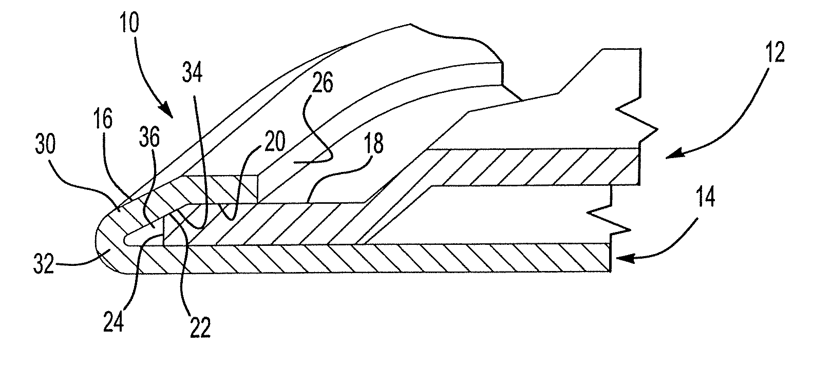
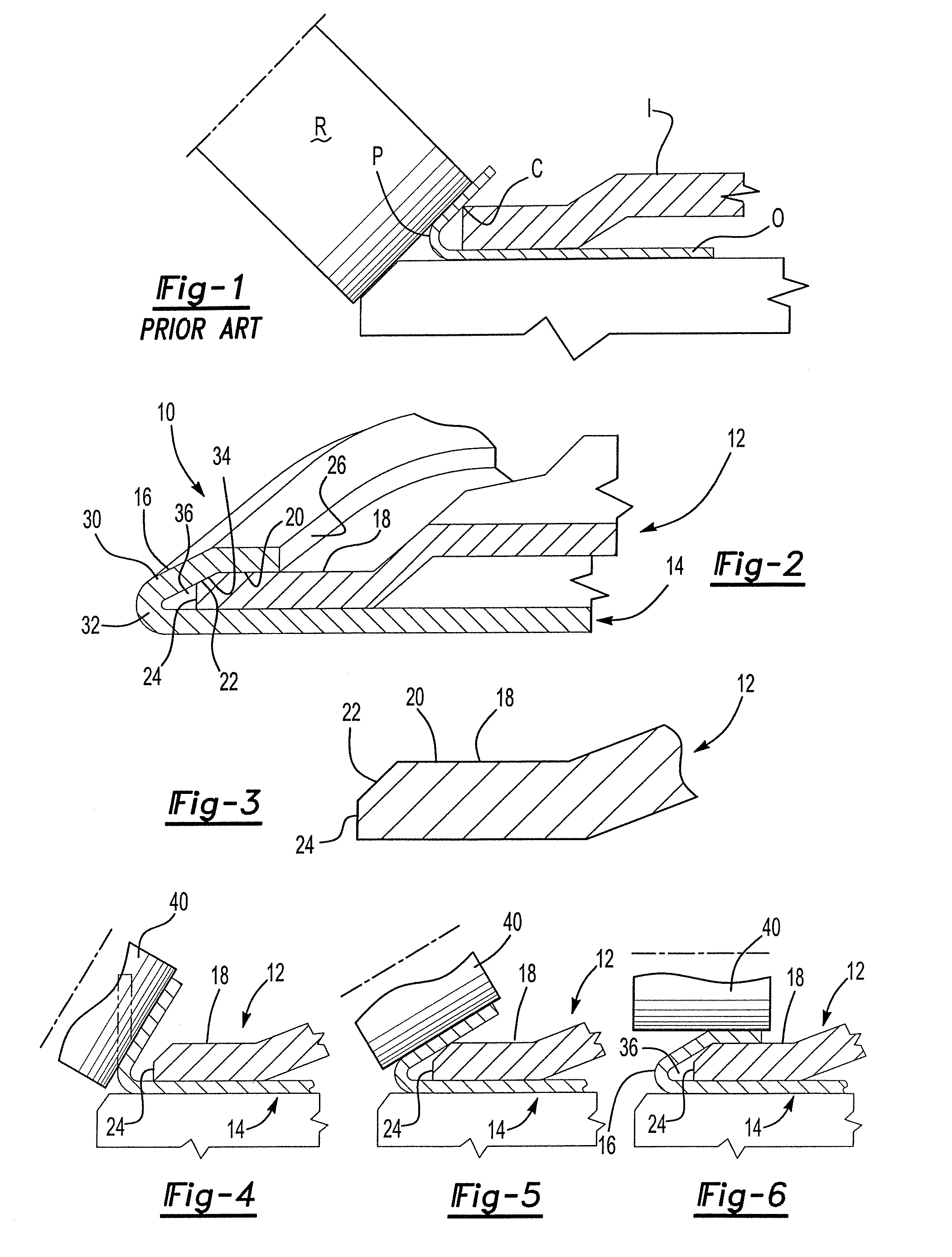
[0023] Referring to FIG. 2, a hem assembly 10 for a vehicle closure panel is shown. An inner panel 12 and outer panel 14 are joined with a peripheral edge 16 of an outer panel being folded back over a perimeter flange 18 of the inner panel 12. The perimeter flange 18 is tightly gripped by the outer panel 14.

[0024] The perimeter flange 18 of the inner panel has an inboard surface 20, a beveled surface 22 and an end surface 24. The peripheral edge 16 of the outer panel 14 has a distal portion 26, a intermediate portion 30 and a bend portion 32. An inner surface 34 of the peripheral edge 16 at the intermediate portion 30 of the outer panel 14 is adjacent to the beveled surface 22 of the inner panel 12. The inner surface 34 of the peripheral edge 16 at the distal portion 26 of the outer panel 14 abuts the inboard surface 20 of the perimeter flange 18 of the inner panel 12. The beveled surface 22 is located between the end surface 24 and the inboard surface 20 of the perimeter flange 18...


PUM

PropertyMeasurementUnit
Angleaaaaaaaaaa
Thicknessaaaaaaaaaa
Angleaaaaaaaaaa

Abstract

A reduced radius hem assembly and method for joining an inner panel and an outer panel together. The inner panel has an outwardly extending perimeter flange comprising an end surface, an inboard surface, and a beveled surface located between the end surface and the inboard surface. The outer panel has a peripheral edge comprising a bend portion, an intermediate portion, and an end portion. In the finished hem assembly, the intermediate portion is adjacent to the beveled surface of the perimeter flange and the end portion overlies a portion of the inboard surface of the perimeter flange. The method provides a reduced radius hem while allowing the peripheral edge of the outer panel to cover the marriage gap and minimizing the potential for interference between the inner panel and the outer panel in the hem assembly.

Description

BACKGROUND OF INVENTION [0001] 1. Field of the Invention [0002] The present invention relates to sheet metal hem flanges and an improved hemming process. [0003] 2. Background Art [0004] Hemming is a production process for joining an outer panel to an inner reinforcement panel. Conventional hemming processes are accomplished by bending a peripheral edge of the outer panel back onto the inner panel. A multiple step process is used to form a hem. In a first step, a peripheral edge of an outer panel is formed to extend substantially perpendicularly relative to the body of the outer panel. In a second step, an inner panel is assembled to the outer panel with a perimeter flange being inserted inside the peripheral edge of the outer panel. In the third step, the peripheral edge of the outer panel is pre-hemmed. Prehemming may be performed by forming the peripheral edge to an acute angle of approximately 45° to extend inwardly over the perimeter flange of the inner panel. Alternatively, the...

Claims


Application Information

Patent Timeline
IPC IPC(8): F16B5/00
CPCB21D39/021F16B5/0096Y10T403/4933Y10T29/53791Y10T29/49915
Inventor MILLER, CRAIGFRIEDMAN, PETER
Owner FORD GLOBAL TECH LLC
Why Eureka
Try Eureka