Umbilical Splint and Method of Use

a splint and splint technology, applied in the field of splints, can solve the problems of difficult to ensure sterility, difficult to keep marbles in place, and deformities of the umbilicus, and achieve the effects of reducing the formation and/or appearance of scars, reducing the formation of pressure, and reducing the formation of scars

Inactive Publication Date: 2016-06-02
VEKIOS ROULA
View PDF5 Cites 1 Cited by
  • Summary
  • Abstract
  • Description
  • Claims
  • Application Information

AI Technical Summary

Benefits of technology

[0009]The umbilical splint is designed to be inserted into the umbilicus at the time of surgery to counteract the forces of scar contracture. In this way, in at least one embodiment, the umbilical splint may be configured to decrease stenosis of the umbilicus following surgery. The umbilical splint may be configured to prevent cosmetic deformities and late infections at the site. In post-partum women, the splint may be inserted immediately post-partum to help shape the umbilicus during retraction of the distended pregnant abdomen. Once inserted, the umbilical splint may be worn periodically or continuously, except for personal hygiene purposes, to aid in the healing process. In some embodiments, the umbilical splint may be maintained within the umbilicus for a pre-determined period of time.
[0010]The shape of the umbilical splint is designed to promote the healing of the umbilicus and to reduce scarring by applying constant pressure to the entire umbilical region. In surgical patients where a scar is present, a silicone gel sheet may be applied to the splint following suture removal to improve the overall cosmesis (i.e. physical appearance) of the scar. Past research has shown that application of silicone to scars, as well as the application of pressure, improves the overall cosmesis of the mature scar.
[0011]The umbilical splint may be configured to have several advantages, such as, resist the forces of scar contracture to maintain an aesthetically pleasing shape and size of the umbilicus, apply pressure to the surrounding scar tissue, and apply silicone gel sheeting in combination with the applied pressure to promote healing. Furthermore, a slow-release antibiotic covering or medicament may be used to decrease the chances of wound infection.
[0012]The overall form of the umbilical splint is designed both to improve the shape of the umbilicus and to retain the splint within the umbilicus. Accordingly, the umbilical splint may be configured with a bulbous section with a pre-determined shape. The bottom bulbous portion may be manufactured out of hard plastic. However, it should be understood that other materials may be used, such as glass, metal, medical ceramic, silicone, medical plastics, minerals, and the like. Furthermore, in some embodiments, the umbilical splint may have a rigid core surrounded by a softer more flexible outer material for improved comfort. For example, the outer material may be a soft, flexible plastic or an alternative material such as medical grade silicone, and the like.
[0016]The shape of the bulbous section may also help to retain the umbilical splint within the umbilicus. In some embodiments, a bulbous section with an asymmetric shape may be better at being retained within the umbilicus or may provide an advantageous distribution of pressure to the surrounding tissue. Finally, in some embodiments, an adhesive may be used or a further mechanism, such as a tape or a bandage, may be placed over the umbilical splint and against the abdominal wall in order to retain the umbilical splint within the umbilicus.
[0017]In some embodiments, the umbilical splint may have an external flange for covering the umbilical opening, protecting against dust and pathogens entering the umbilical opening. The external flange may also apply direct pressure to the external circumferential umbilical scar. In this manner, the external flange may reduce the formation and / or the appearance of scars. Furthermore, the external flange may help retain any medicament placed inside the umbilicus prior to the insertion of the umbilical splint.

Problems solved by technology

This can lead to deformities of the umbilicus, as well as infections.
However, marbles are difficult to keep in place and may be difficult to ensure sterility.
Furthermore, foam earplugs are not stiff enough to counteract the forces of scar contracture and can lead to infection due to its porous nature.

Method used


Image

  • Umbilical Splint and Method of Use
  • Umbilical Splint and Method of Use
  • Umbilical Splint and Method of Use

Examples


Embodiment Construction

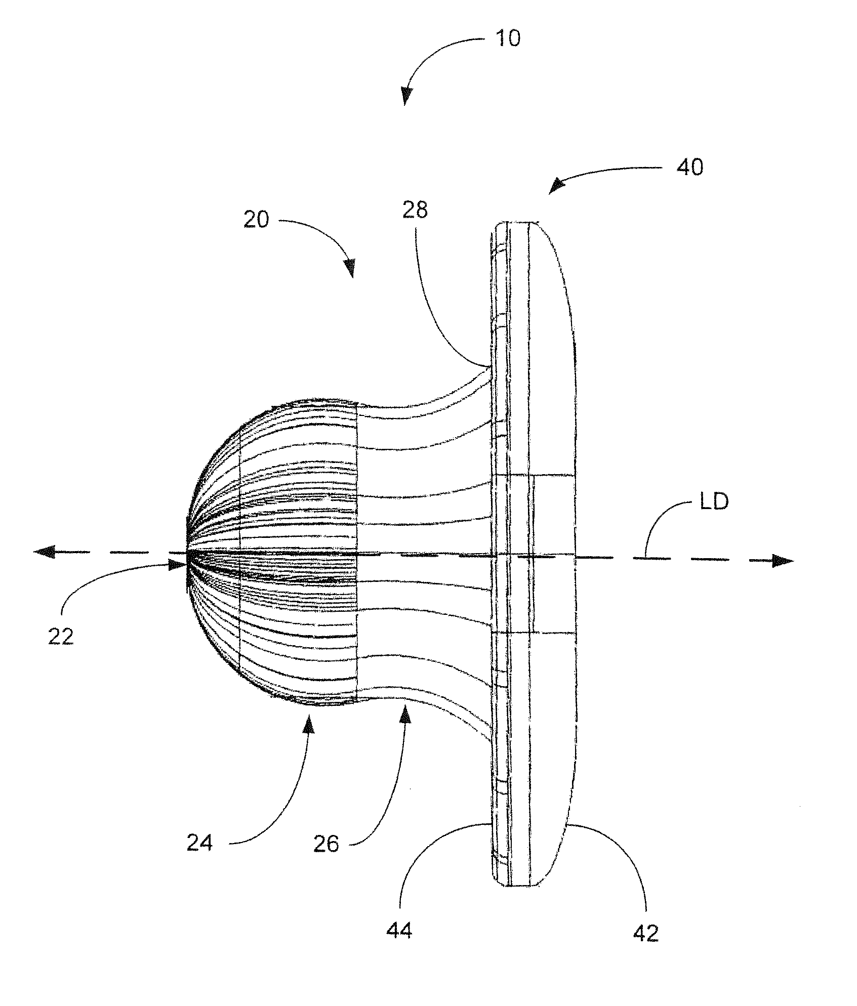
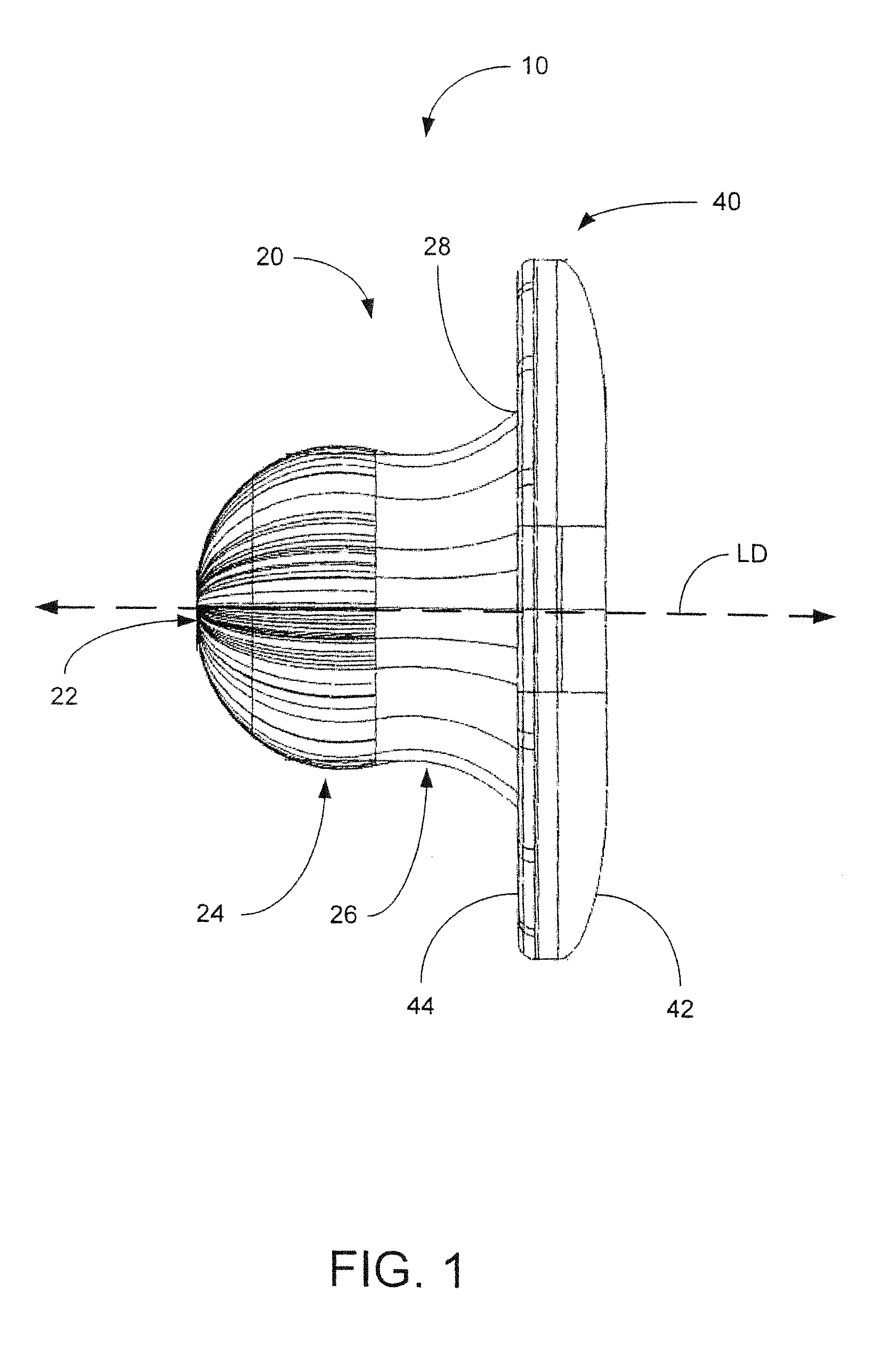
[0042]Referring now to FIG. 1, an umbilical splint 10 is shown in accordance with an embodiment of the present invention. The umbilical splint 10 is configured with an insertion portion 20 terminating at an insertion end 22 and an external flange 40.

[0043]The insertion portion 20 extends in a longitudinal direction LD, shown in dashed lines, for insertion into an umbilicus. The insertion portion 20 includes an insertion end 22, a bulbous section 24 and a retaining section 26. The bulbous section 24 is disposed between the insertion end 22 and the retaining section 26.

[0044]The umbilical splint 10 may also include an external flange 40. The external flange 40 is configured with an external surface 42 and an underside surface 44. The underside surface 44 of the external flange 40 faces the insertion end 22 of the insertion portion 20. The insertion portion 20 and the external flange 40 may be joined at an intersection 28.

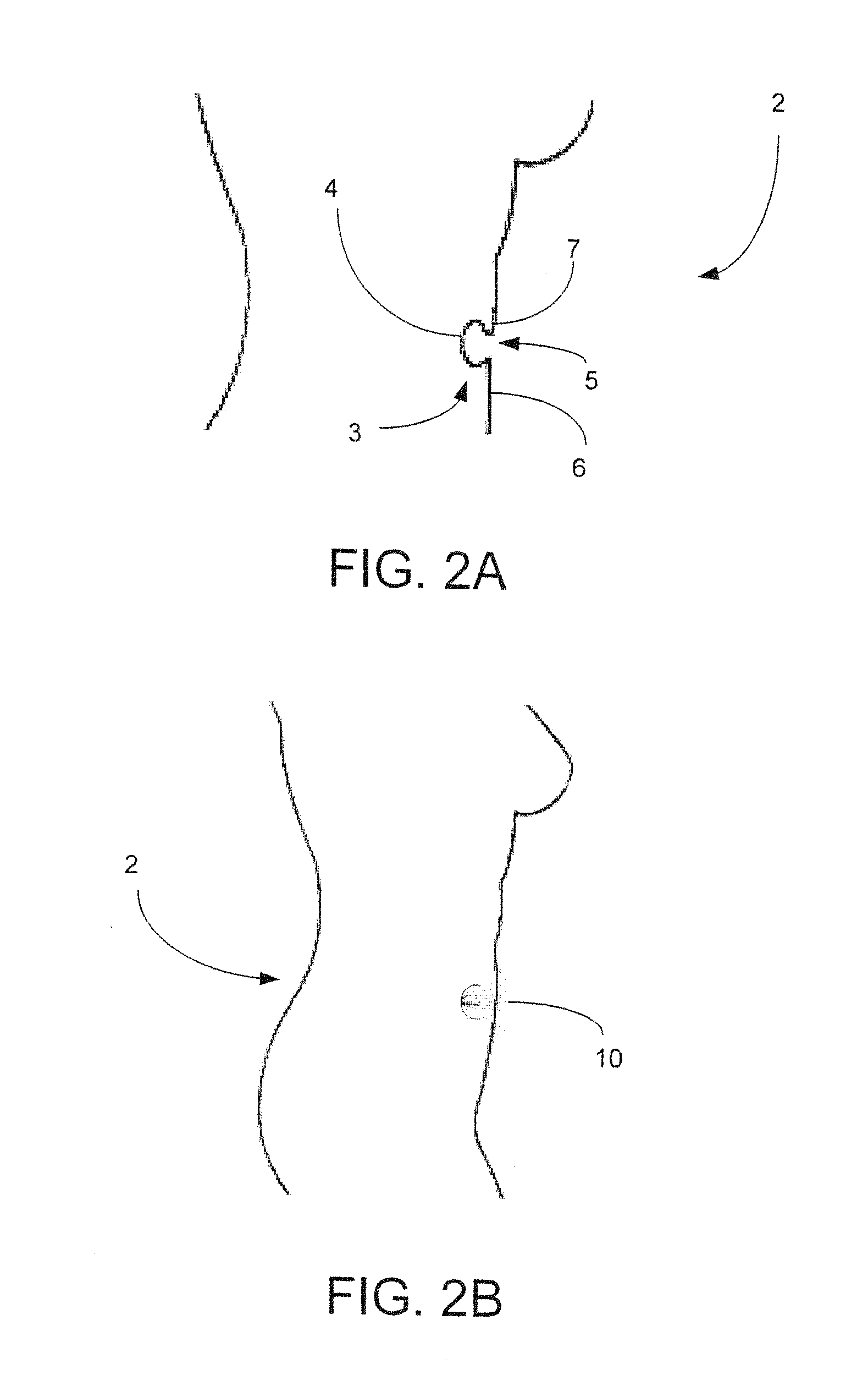
[0045]As seen in FIG. 2A, a patient 2 has an umbilicus 3 (i.e. a...


PUM


Abstract

A use of an umbilical splint for shaping an umbilicus after an abdominal operation is described. The umbilical splint may comprise an insertion portion extending in a longitudinal direction and terminating at an insertion end for insertion into the umbilicus. Furthermore, the insertion portion may comprise a bulbous section near the insertion end. The bulbous section may be operable to apply pressure to a tissue of the umbilicus after the abdominal operation. The insertion portion may have different cross-sectional shapes including circular and oval. Finally, the insertion portion may be configured to engage the umbilicus such that the umbilical splint is retained within the umbilicus.

Description

RELATED APPLICATIONS[0001]This application is a continuation of U.S. patent application Ser. No. 13 / 374,669, filed Jan. 6, 2012, which is hereby incorporated by reference.FIELD OF THE INVENTION[0002]This invention relates to an umbilical splint, and more particularly towards an umbilical splint for post-operative care and methods of use.BACKGROUND OF THE INVENTION[0003]During certain types of abdominal surgery, incisions are made in the umbilicus or the surrounding umbilical (belly button) region. Examples of such procedures include abdominoplasty (i.e. tummy tuck), panniculectomy, Transverse Rectus Abdominis Myocutaneous (TRAM) flap procedures, endoscopic surgeries, and the like. Circumferential umbilical incisions can lead to contracture and closure of the umbilicus or umbilical opening due to the physiological forces of scar contracture. This can lead to deformities of the umbilicus, as well as infections.[0004]Deformity of the umbilicus can also occur after pregnancy, especially...

Claims


Application Information

Patent Timeline
Patent Type & Authority Applications(United States)
IPC IPC(8): A61F5/30A61B17/00
CPCA61F5/30A61B2017/00637A61B17/0057A61B2017/00654A61B2017/00659A61B2017/00893A61B17/08
Inventor VEKLOS, ROULAMEATHREL, KIMBERLEY
Owner VEKIOS ROULA
Why Eureka
Try Eureka