
Methods for monitoring the formation and transport of an acidizing fluid using opticoanalytical devices

an opticoanalytical device and acidizing fluid technology, applied in the field of fluid monitoring, can solve the problems of difficult off-line laboratory analysis, difficult to perform off-line laboratory analyses, and large sample preparation requirements

Active Publication Date: 2013-02-07
HALLIBURTON ENERGY SERVICES INC
View PDF32 Cites 39 Cited by
  • Summary
  • Abstract
  • Description
  • Claims
  • Application Information

AI Technical Summary

Benefits of technology

The present invention provides methods for monitoring fluids in real-time during various operations in a subterranean formation. These methods involve using opticoanalytical devices to monitor characteristics of the fluids, such as their composition, pH, and viscosity. This allows for real-time monitoring of the fluids as they are introduced into the formation, providing valuable information for making decisions and adjusting the fluids' characteristics in real-time. The methods can be used in various applications such as drilling, wellbore cleaning, and hydraulic fracturing.

Problems solved by technology

Depending on the analysis needed, such an approach can take hours to days to complete, and even in the best case scenario, a job can often be completed prior to the analysis being obtained.
Furthermore, off-line laboratory analyses can sometimes be difficult to perform, require extensive sample preparation and present hazards to personnel performing the analyses.
Bacterial analyses can particularly take a long time to complete, since culturing of a bacterial sample is usually needed to obtain satisfactory results.
Although off-line, retrospective analyses can be satisfactory in certain cases, they do not generally allow real-time or near real-time, proactive control of a subterranean operation to take place.
That is, off-line, retrospective analyses do not allow active control of a subterranean operation to take place, at least without significant process disruption occurring white awaiting the results of an analysis.
In many subterranean operations, the lack of real-time or near real-time, proactive control can be exceedingly detrimental to the intended outcome of the subterranean operation.
For example, if an incorrect treatment fluid is introduced into a subterranean formation, or if a correct treatment fluid having a desired composition but at least one undesired characteristic (e.g., the wrong concentration of a desired component, the wrong viscosity, the wrong pH, an interfering impurity, a wrong sag potential, the wrong kind or concentration of proppant particulates, bacterial contamination and / or the like) is introduced into a subterranean formation, the subterranean operation can produce an ineffective outcome or a less effective outcome than desired.
Worse yet, if an incorrect treatment fluid or a treatment fluid having an undesired characteristic is introduced into the subterranean formation, damage to the formation can occur in some cases.
Such damage can sometimes result in the abandonment of a wellbore penetrating the subterranean formation, or a remediation operation can sometimes be needed to at least partially repair the damage.
In either case, the consequences of introducing the wrong treatment fluid into a subterranean formation can have serious financial implications and result in considerable production delays.
Off-line, retrospective analyses can also be unsatisfactory for determining the true suitability of a treatment fluid for performing a treatment operation or for evaluating the true effectiveness of a treatment operation.
Specifically, once removed from their subterranean environment and transported to a laboratory, the characteristics of a treatment fluid sample can change, thereby making the properties of the sample non-indicative of the true effect produced by the treatment fluid in the subterranean formation.
Similar issues also can be encountered in the analysis of treatment fluids before they are introduced into a subterranean formation.
For example, if an incorrect source material or the wrong quality and / or quantity of a source material is used to form a treatment fluid, it is highly likely that the treatment fluid will have an undesired characteristic.
As an added concern, the significant volumes of fluids produced from a subterranean formation can present enormous waste disposal issues, particularly in view of increasingly strict environmental regulations regarding the disposal of produced water and other types of waste water.
The inability to rapidly analyze produced fluids can make the recycling or disposal of these fluids exceedingly problematic, since they must be stored until analyses can be completed.
As previously indicated, even when an analysis has been completed, there is no guarantee that the sample will remain indicative of the produced bulk fluid.
Specifically, issues such as, for example, scaling, impurity buildup, bacterial growth and the like can impede processes in which fluids are used, and even damage process equipment in certain cases.
For example, water streams used in cooling towers and like processes can become highly corrosive over time and become susceptible to scale formation and bacterial growth.
Corrosion and scale formation can damage pipelines through which the water is flowing and potentially lead to system breakdowns.
Similar issues can be encountered for fluids subjected to other types of environments.
Thus, there can be a delay in obtaining an analysis due to sample preparation time, even discounting the transit time of the sample to a laboratory.
Furthermore, the transitioning of spectroscopic instruments from a laboratory into a field or process environment can be expensive and complex.
Furthermore, sample preparation, when required, can be difficult under field analysis conditions.
The difficulty of performing sample preparation in the field can be especially problematic in the presence of interfering materials, which can further complicate conventional spectroscopic analyses.
Quantitative spectroscopic measurements can be particularly challenging in both field and laboratory settings due to the need for precision and accuracy in sample preparation and spectral interpretation.

Method used


Image

  • Methods for monitoring the formation and transport of an acidizing fluid using opticoanalytical devices
  • Methods for monitoring the formation and transport of an acidizing fluid using opticoanalytical devices
  • Methods for monitoring the formation and transport of an acidizing fluid using opticoanalytical devices

Examples


Embodiment Construction

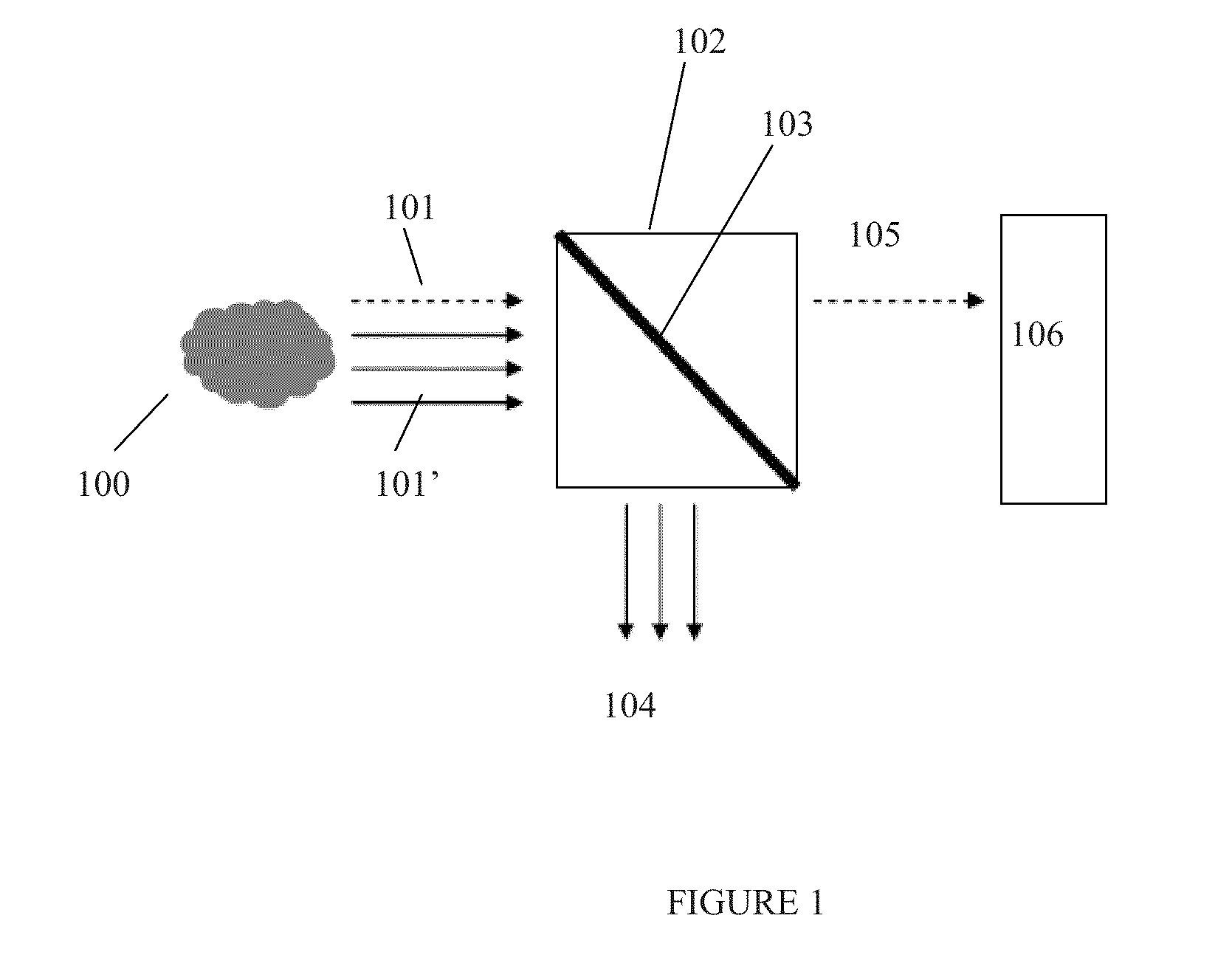
[0039]The present invention generally relates to methods for the monitoring of fluids in or near real-time, and, more specifically, to methods for monitoring fluids prior to, during or after their introduction into a subterranean formation and / or to methods for monitoring produced fluids from a subterranean formation.

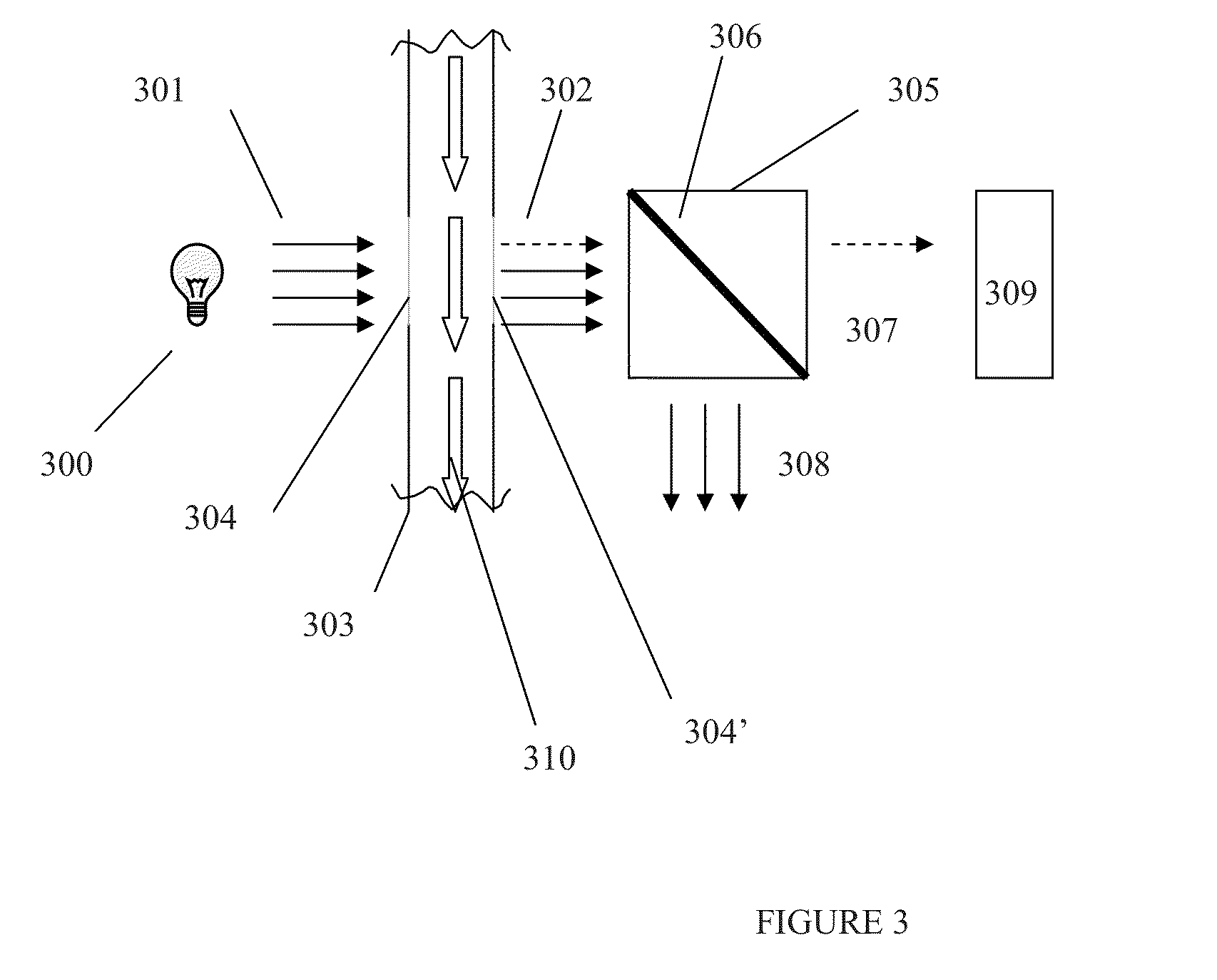
[0040]Various embodiments described herein utilize opticoanalytical devices that can be utilized for the real-time or near real-time monitoring of fluids that are ultimately introduced into a subterranean formation. Likewise, these opticoanalytical devices can be used to monitor fluids that are produced from a subterranean formation (including both flow back fluids, formation fluids, and combinations thereof) or to monitor and regulate fluids that are used in various processes. These devices, which are described in more detail herein, can advantageously provide a measure of real-time or near real-time quality control over the introduction of fluids into a subterranean f...


PUM


Abstract

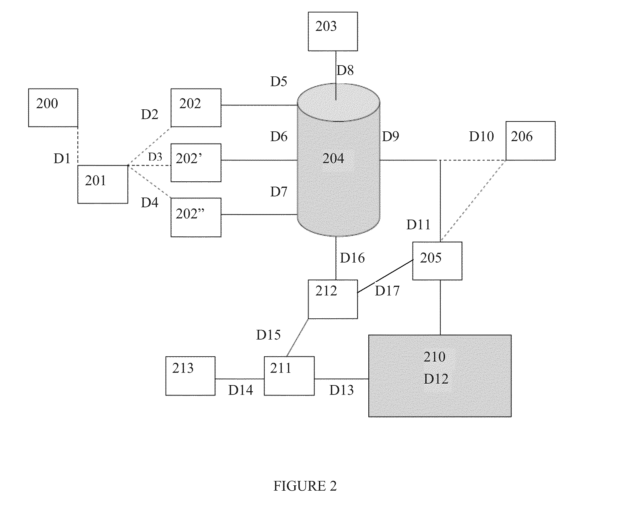
In or near real-time monitoring of fluids can take place using an opticoanalytical device that is configured for monitoring the fluid. Fluids can be monitored prior to or during their introduction into a subterranean formation using the opticoanalytical devices. Produced fluids from a subterranean formation can be monitored in a like manner. The methods can comprise providing at least one acid; combining the at least one acid with a base fluid to form an acidizing fluid; and monitoring a characteristic of the acidizing fluid using a first opticoanalytical device that is in optical communication with a flow pathway for transporting the acidizing fluid.

Description

BACKGROUND[0001]The present invention generally relates to methods for the monitoring of fluids in or near real-time, and, more specifically, to methods for monitoring fluids prior to, during or after their introduction into a subterranean formation and / or to methods for monitoring produced fluids from a subterranean formation.[0002]When conducting operations within a subterranean formation, it can be important to precisely know the characteristics of a fluid or other component present in or being introduced into the formation. Typically, the analysis of fluids and other components being introduced into a subterranean formation has been conducted off-line using laboratory analyses (e.g., spectroscopic and / or wet chemical methods). These analyses can be conducted on fluid samples being introduced into the subterranean formation or on flow back fluid samples being produced from the subterranean formation after a treatment operation has occurred. Depending on the analysis needed, such ...

Claims


Application Information

Patent Timeline
IPC IPC(8): E21B43/12G01N21/00
CPCC02F1/008C09K8/72G01J3/28C02F2103/02C02F2103/10C02F2209/001E21B47/102C02F2209/36C02F2303/04C02F2303/08C02F2303/20C02F2303/22C02F2209/003E21B47/113E21B43/28
Inventor FREESE, ROBERT P.JONES, CHRISTOPHER M.PELLETIER, MICHAEL T.DAUSSIN, RORY D.HAYWORTH, ROBERT D.
Owner HALLIBURTON ENERGY SERVICES INC
Learn More