Extendable and deformable charging system

a charging system and extension coil technology, applied in the direction of charging stations, electric vehicle charging technology, transportation and packaging, etc., can solve the problem of very dependent system efficiency, and achieve the effect of reducing air gap or proximity distance, increasing or optimizing energy transfer efficiency for battery charging, and reducing inadvertent damag

Active Publication Date: 2013-02-07
SCHNEIDER ELECTRIC USA INC
View PDF12 Cites 75 Cited by
  • Summary
  • Abstract
  • Description
  • Claims
  • Application Information

AI Technical Summary

Benefits of technology

[0006]Aspects of the present invention offer improvements to induction charging systems for electric vehicles by providing a carrier protecting and allowing the primary, i.e. charging, coil to be moved closer to the secondary, i.e. sensing, coil of the electric vehicle to increase or optimize the efficiency of energy transfer for battery charging. In various aspects of the present invention the carrier is retractable to be flush with a floor surface, meaning any surface on which the vehicle normally rests and is exte...

Problems solved by technology

While induction charging can offer advantages over other charging formats, one inescapable limitation of induction chargi...

Method used


Image

  • Extendable and deformable charging system
  • Extendable and deformable charging system
  • Extendable and deformable charging system

Examples


Embodiment Construction

[0017]Words of degree, such as “about”, “substantially”, and the like are used herein in the sense of “at, or nearly at, when given the manufacturing, design, and material tolerances inherent in the stated circumstances” and are used to prevent the unscrupulous infringer from unfairly taking advantage of the invention disclosure where exact or absolute figures and operational or structural relationships are stated as an aid to understanding the invention.

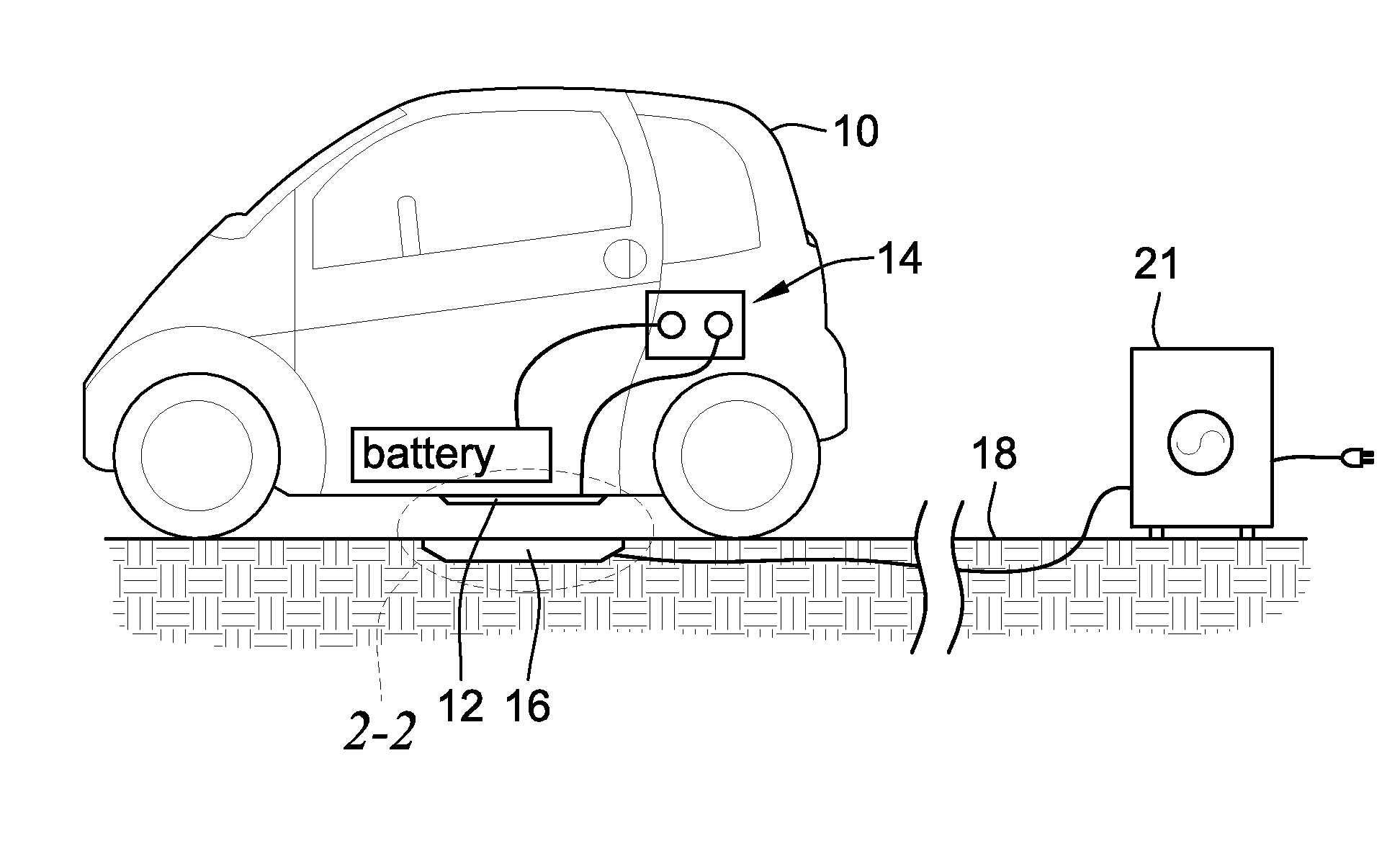
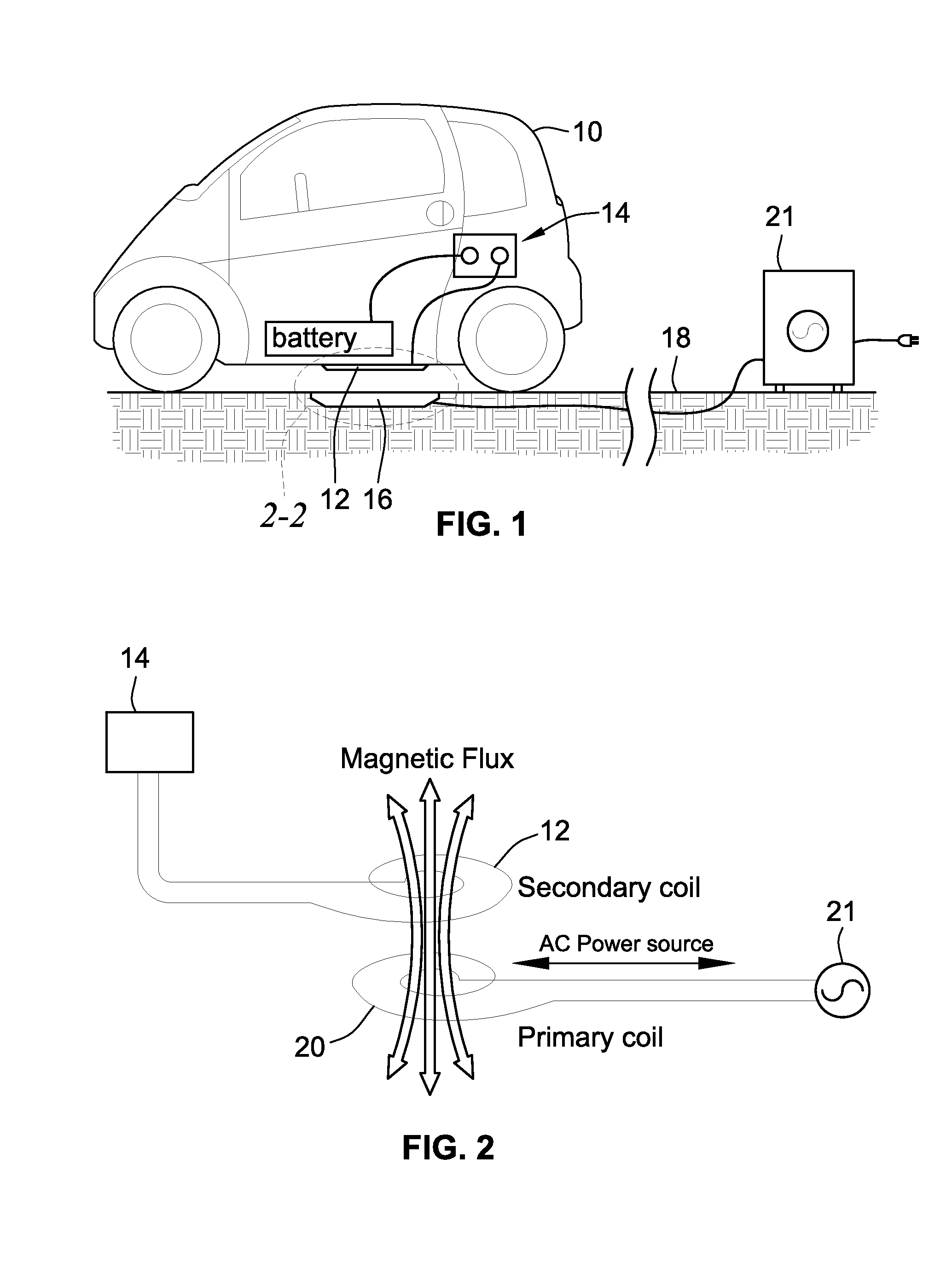
[0018]Referencing FIG. 1, an electric vehicle 10 is carrying a secondary coil 12 for its battery charging electrical and / or electronic system 14 and is parked over a charging station 16 mounted in a floor 18, the floor being the surface the vehicle rests on, whether of earthen or man-made structures such as various forms of pavement. Referencing also the schematic of FIG. 2, the charging station 16 carries the primary, or charging, coil 20 which is connected to a preferably remotely located power grid apparatus 21 supplying the AC p...


PUM


Abstract

A subsurface mounted inductive charging coil system for electric vehicles accommodates the gap distance between primary charging coil and secondary coil on the vehicle with an extendable primary coil carrier. The system protects the primary coil when exposed by mounting on a deformable and elastic structure. By keeping the primary coil normally hidden in a deformable and elastic structure several advantages are obtained. The extendable structure is preferably a low pressure inflatable bladder or membrane in the floor for carrying, protecting, and extending the primary coil.

Description

BACKGROUND OF THE INVENTION[0001]1. Field of the Invention[0002]The present invention relates generally to electric vehicle charging systems. The present invention relates particularly to induction coil based electric vehicle charging systems for parked vehicles or other stationary objects.[0003]2. Discussion of Related Art[0004]Induction charging of electric vehicles has been proposed in the art. In an induction charging system a primary coil induces a magnetic field into a secondary coil which produces a current subsequently used by on-board electronics of the electric vehicle to charge its batteries. While induction charging can offer advantages over other charging formats, one inescapable limitation of induction charging systems is that efficiency of the systems is very dependent upon proximity of the coils to each other, i.e. the gap distance. Less than two inches of gap is considered efficacious for a through-air proximity distance to achieve over 90% efficiency in induction c...

Claims


Application Information

Patent Timeline
IPC IPC(8): H02J7/00
CPCB60L11/1829Y02T10/7005Y02T90/125Y02T90/121Y02T90/14Y02T90/122B60L11/182Y02T90/12Y02T10/7072B60L53/38B60L53/126Y02T10/70
Inventor GIBBONS, JR., DONALD GREGORY
Owner SCHNEIDER ELECTRIC USA INC
Why Eureka
Try Eureka