
Eureka
For R&D, Eureka makes reading and utilizing patents & technical documents easy.
Eureka AIR
Designed for self-driven R&D workflows. Generate viable solutions, solve complex R&D challenges, empower your innovation with AI.

Eureka Materials
Designed for material experts only. Revolutionize your material R&D, from search, analyze, to developing new materials.

TechResearch
Generate reliable direction feasibility study reports for your R&D in just a few steps.

TechSeek
Discover and master advanced knowledge NOW. Basics, ideas, possibilities, all at once.

TechMind
As an expert in R&D Theories, TechMind can generates customized viable solutions instantly.

TechRisk
Analyze your overall solution with one click, know your potential R&D risks in advance.

TechMonitor
Get weekly tech updates, stay abreast of the latest tech innovations and key insights.
Acoustic wave filter
- Summary
- Abstract
- Description
- Claims
- Application Information
AI Technical Summary
Benefits of technology
Problems solved by technology
Method used
Image

Examples
first embodiment
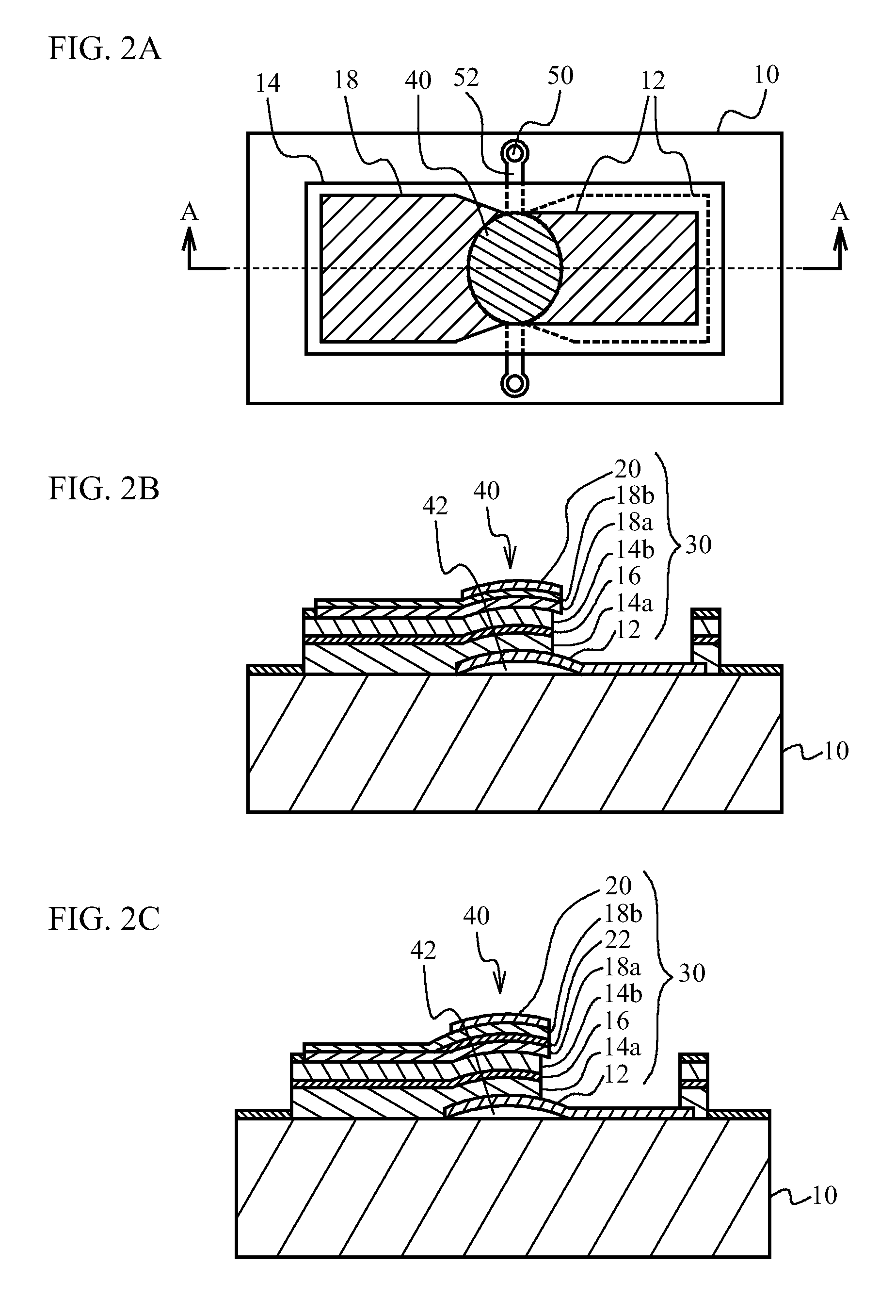
[0045]FIGS. 7A through 7C are schematic views illustrating a structure of a piezoelectric thin film resonator in the acoustic wave filter in accordance with the first embodiment, and correspond to FIGS. 2A through 2C of the comparative example respectively. The structure of the piezoelectric thin film resonator in accordance with the first embodiment is basically the same as that of the comparative example, but is different in that a mass load film for the frequency control (hereinafter, a second mass load film 24) is formed in the resonance region 40 located between the upper electrode 18 and the frequency adjusting film 20. The second mass load film 24 is used for making resonance frequencies of resonators constituting the acoustic wave filter have different values as described later. In acoustic wave filters (filters A, B and G) in accordance with the comparative example, the second mass load film 24 is not used.
[0046]FIGS. 8A through 8F are schematic views illustrating a detail ...
second embodiment
[0057]The second embodiment is an embodiment in which the configuration of the ladder filter is changed.
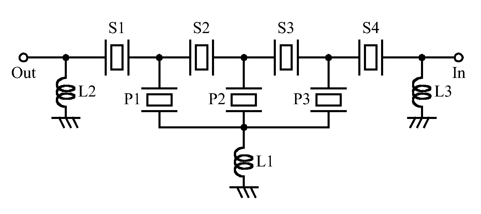
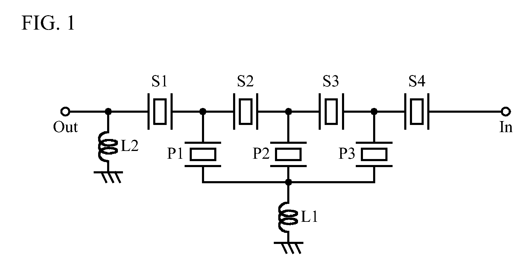
[0058]FIG. 11 is a circuit diagram illustrating a configuration of an acoustic wave filter in accordance with a second embodiment (filter D). The circuit configuration of the acoustic wave filter in accordance with the second embodiment is basically the same as that of the acoustic wave filter in accordance with the first embodiment (FIG. 1), except that in addition to inductors L1 and L2, an inductor L3, one end of which is connected to ground, is connected between the input terminal In and the series resonator S4. The structure of the piezoelectric thin film resonator which constitutes the ladder filter is the same as that of the first embodiment (FIG. 7, FIG. 8). Resonance frequencies of resonators are shown in columns of filter D in FIG. 5.
[0059]FIGS. 12A through 12C are graphs illustrating a comparison of bandpass characteristics between the acoustic wave filter in accordance...
third embodiment
[0063]A third embodiment is an embodiment using a piezoelectric thin film resonator in which the piezoelectricity of the piezoelectric film is improved.
[0064]A circuit configuration of acoustic wave filters in accordance with the third embodiment (filters E, F) is the same as that of the second embodiment (FIG. 11), and a structure of the piezoelectric thin film resonator constituting the ladder filter is the same as those of the first and second embodiments (FIG. 7, FIG. 8). Different from the first and second embodiments, an element to increase the piezoelectric constant (e33) is added to piezoelectric films (the first piezoelectric film 14a and the second piezoelectric film 14b) of the piezoelectric thin film resonator. As the element to increase the piezoelectric constant, alkali earth metal (scandium (Sc) and the like), rare-earth metal (erbium (Er) and the like) can be used for example.
[0065]In the piezoelectric thin film resonator in accordance with the comparative example an...
PUM
 Abstract
Description
Claims
Application Information
 - R&D Engineer
- R&D Manager
- IP Professional
- Industry Leading Data Capabilities
- Powerful AI technology
- Patent DNA Extraction
Browse by: Latest US Patents, China's latest patents, Technical Efficacy Thesaurus, Application Domain, Technology Topic, Popular Technical Reports.
© 2024 PatSnap. All rights reserved.Legal|Privacy policy|Modern Slavery Act Transparency Statement|Sitemap|About US| Contact US: help@patsnap.com