
Event driven context switching in passive radio frequency identification tags

a radio frequency identification and context switching technology, applied in the field of passive, batteryless, rfid tags, can solve the problems of high cost of system requiring onboard processing and/or memory, difficult design, program and installation, etc., and achieve the effect of simple configuration and simple deactivation of id devices

Inactive Publication Date: 2013-02-07
R F KEEPER
View PDF1 Cites 49 Cited by
  • Summary
  • Abstract
  • Description
  • Claims
  • Application Information

AI Technical Summary

Benefits of technology

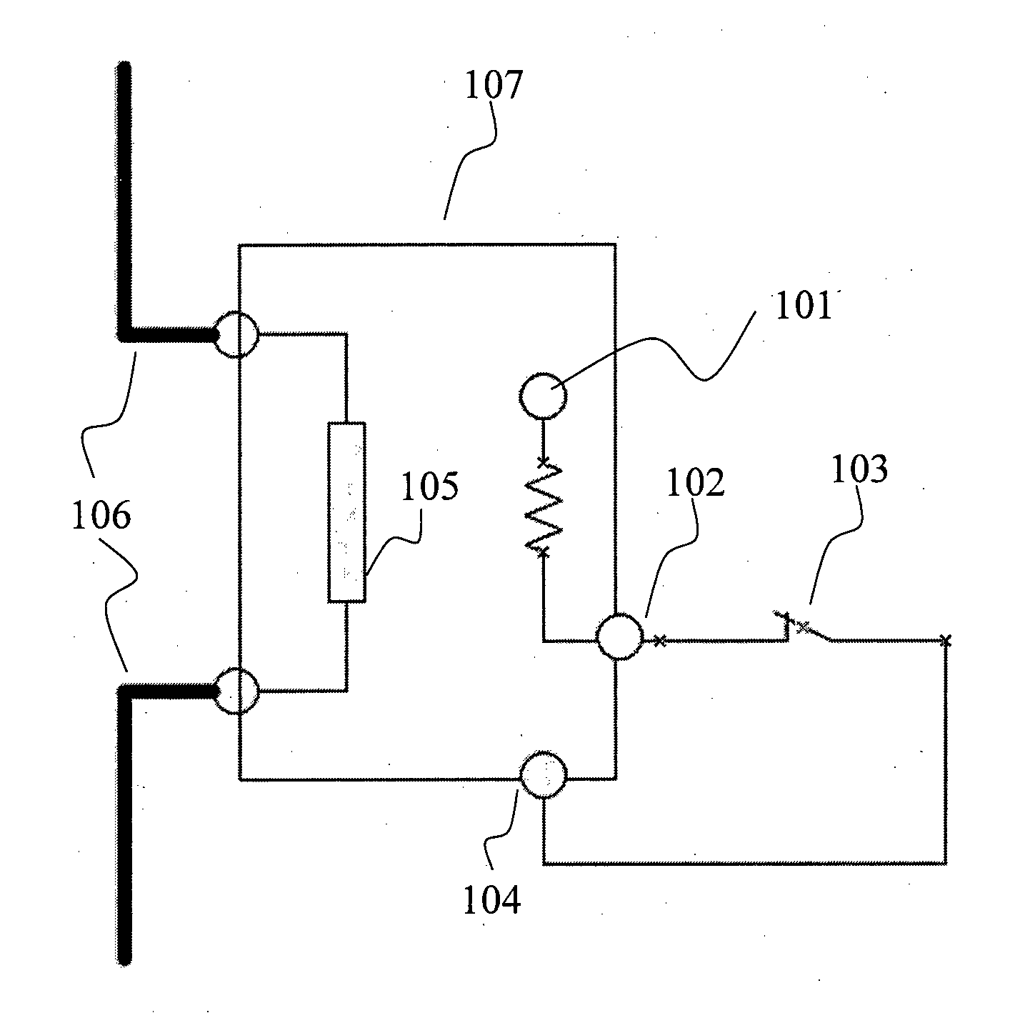
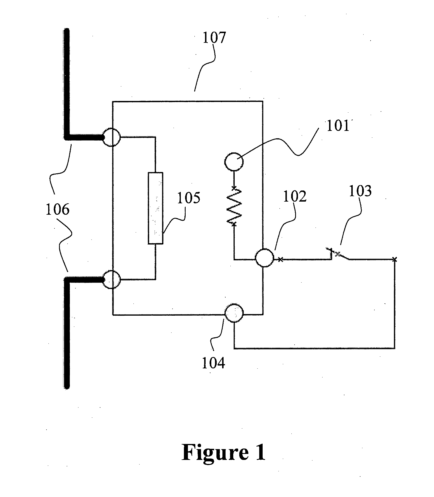
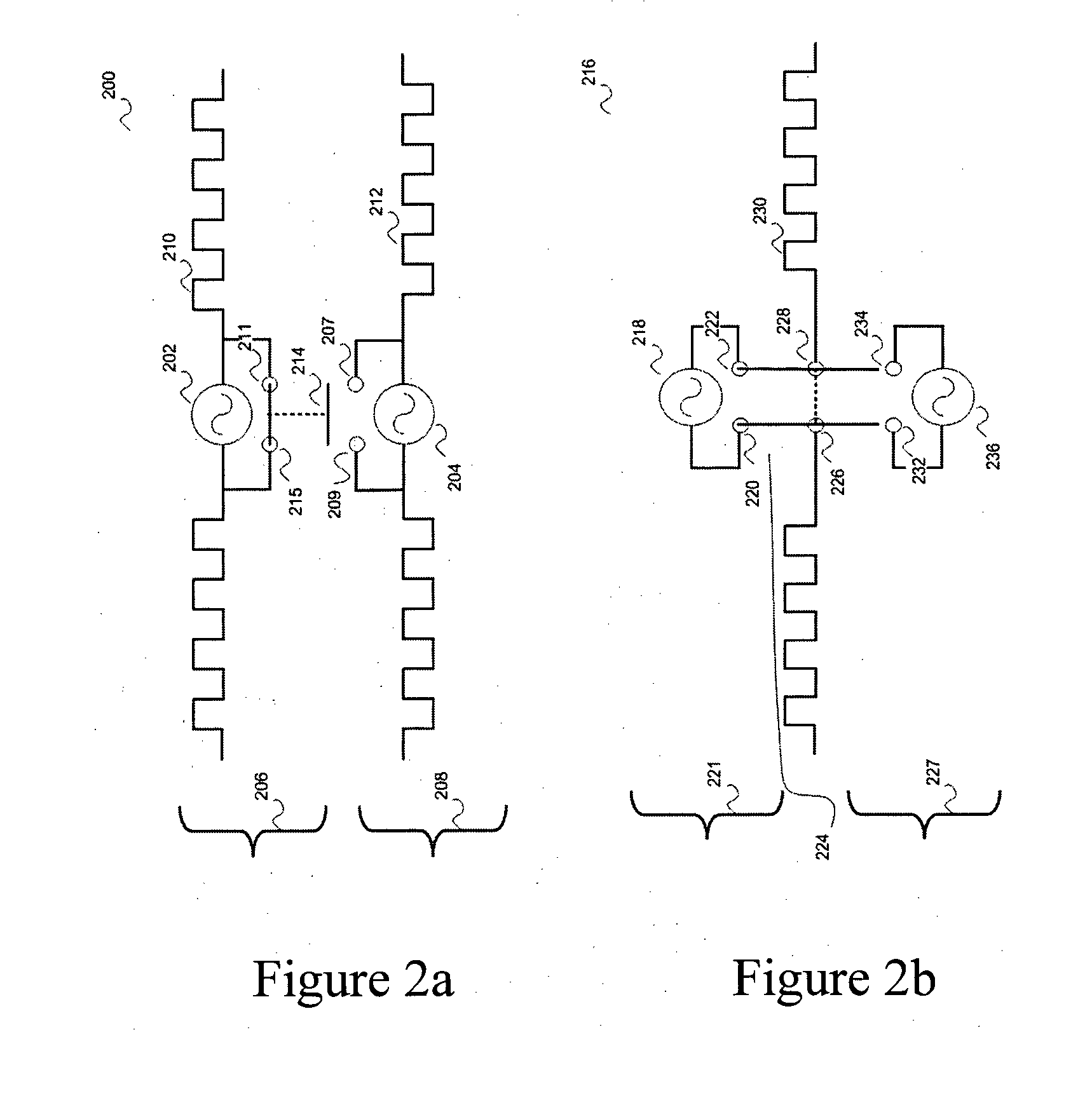
The present invention is about a passive RFID tag device that can be used for external monitoring and information transmission to an RFID reader. The tag includes a sensor device and an irreversible switch that can change its state due to external events such as laundering, tampering, or heating. The switch state can be transmitted to the reader by activating or deactivating one or more auxiliary RFID tags. This transmission method helps to ensure the extremely low cost of the RFID tags and does not require any modification of the tags themselves. The primary tag is deactivated when the switch moves to its second position, allowing the RFID reader to read the ID of the auxiliary tag and thereby sense the external event. The sensed information is provided to the reader through the specific ID that is transmitted.

Problems solved by technology

We stress the point that if measured information is not either stored in some way or read by an external reader, it will be lost.
While all the aforementioned devices may be effective in the execution of the specific applications they are utilized for, they all have a number of drawbacks.
Systems requiring onboard processing and / or memory are expensive and difficult to design, program and install and generally require battery power and / or periodic reading.

Method used


Image

  • Event driven context switching in passive radio frequency identification tags
  • Event driven context switching in passive radio frequency identification tags
  • Event driven context switching in passive radio frequency identification tags

Examples


Embodiment Construction

[0058]In the following description, vaious aspects of the invention will be described. For the purposes of explanation, specific configurations and details are set forth in order to provide a thorough understanding of the invention. However, it will be also apparent to one skilled in the art that the invention may be practiced without specific details presented herein. Furthermore, well-known features may be omitted or simplified in order not to obscure the invention.

[0059]The term ‘plurality’ refers hereinafter to any positive integer e.g, 1, 5, or 10 or any other number.

[0060]The term ‘RFID’ hereinafter refers to radio-frequency identification or the system of object identification and tracking known as such.

[0061]The term ‘switch’ hereinafter refers to a mechanical, electrical, chemical, or other means of making and breaking electrical contact between two conductors.

[0062]The term ‘subset’ of a first group refers to a second group consisting solely of elements of the first group....


PUM


Abstract

The invention relates to an event driven content switching technology in a passive, batteryless radio frequency identification (RFID) tag. The RFID tag device monitors the occurence of an external event such as a change in the environment. The switching of the context of the tag is effected by sensors incorporated in the tag. An external event triggers the switch. An RFID reader may subsequently read out the occurrence of the event due to the switch change. Different alignments of the switch could bring about the closing or opening of specific electronic circuits within the RFID tag that effect the storing of information in a selected memory, or changing the ID transmitted by the tag. In a particular embodiment this latter is accomplished by shorting one or the other of two RFID tag antennas. When one antenna is shorted, the second tag's ID is sent, and vice versa.

Description

FIELD OF THE INVENTION[0001]The invention relates to radio frequency identification (RFID) tags in general, and more particularly to a passive, battery-less, RFID tag provided with sensing capabilities and the ability to store sensed data and transmit it to standard RFID readers. Information can be stored concerning events that occur, without presence of an energy source (such as an RFID reader). At a later point this information can be retrieved using a standard RFID reader.BACKGROUND OF THE INVENTION[0002]A passive Radio Frequency Identification (RFID) tag is an integrated circuit combined with an antenna structured such as to allow the RFID tag to be attached to an object to be tracked. The tag antenna picks up signals from an RFID reader and reflects the signal, usually with additional data encoded by modulation of the reflected signal (the additional data being a product code, a unique serial number, or other customized information).[0003]A Radio Frequency Identification (RFID)...

Claims


Application Information

Patent Timeline
IPC IPC(8): G06K7/01G06K19/073
CPCG06K19/0716G06K19/07767G06K19/07345G08B13/2434G08B13/2448G08B13/2417
Inventor RAZ, SHIMIHAYO, GUY
Owner R F KEEPER
Learn More