
Multigrid pressure solver for fluid simulation

a multi-grid pressure solver and fluid simulation technology, applied in the field of can solve the problems of loss of interesting features produced from simulation of a full three-dimensional model, limited conventional techniques employed for free surface water simulation, etc., and achieve the effect of simplifying computations and maintaining accuracy

Active Publication Date: 2013-02-07
NVIDIA CORP
View PDF5 Cites 5 Cited by
  • Summary
  • Abstract
  • Description
  • Claims
  • Application Information

AI Technical Summary

Benefits of technology

The present invention introduces a system and method for generating a multigrid for fluid simulation. This method involves obtaining first level-set field values for a three-dimensional model of a fluid volume represented as a first two-dimensional grid of columns. The first level-set field values are then downsampled to generate second level-set field values for a second two-dimensional grid of columns, which is coarser than the first grid. The second level-set field values are further downsampled to generate third level-set field values for a third two-dimensional grid of columns, which is coarser than the first and second grids. The advantage of this technique is that it enables real-time simulation of free surface water movements and produces detailed water movement results by providing a hierarchy of increasingly coarser representations of the model. The accurate pressure values computed for different regions of the model ensure simulation results that retain detailed features of the water movement.

Problems solved by technology

Conventional techniques employed for free surface water simulations are limited to off-line computation due to the complexity of the models and the simulation performance needs.
However, interesting features produced from simulation of a full three-dimensional model, such as splashes and overturning waves are lost because the two-and-a-half dimensional representation cannot capture details of the water movement.

Method used


Image

  • Multigrid pressure solver for fluid simulation
  • Multigrid pressure solver for fluid simulation
  • Multigrid pressure solver for fluid simulation

Examples


Embodiment Construction

[0022]In the following description, numerous specific details are set forth to provide a more thorough understanding of the present invention. However, it will be apparent to one of skill in the art that the present invention may be practiced without one or more of these specific details. In other instances, well-known features have not been described in order to avoid obscuring the present invention.

System Overview

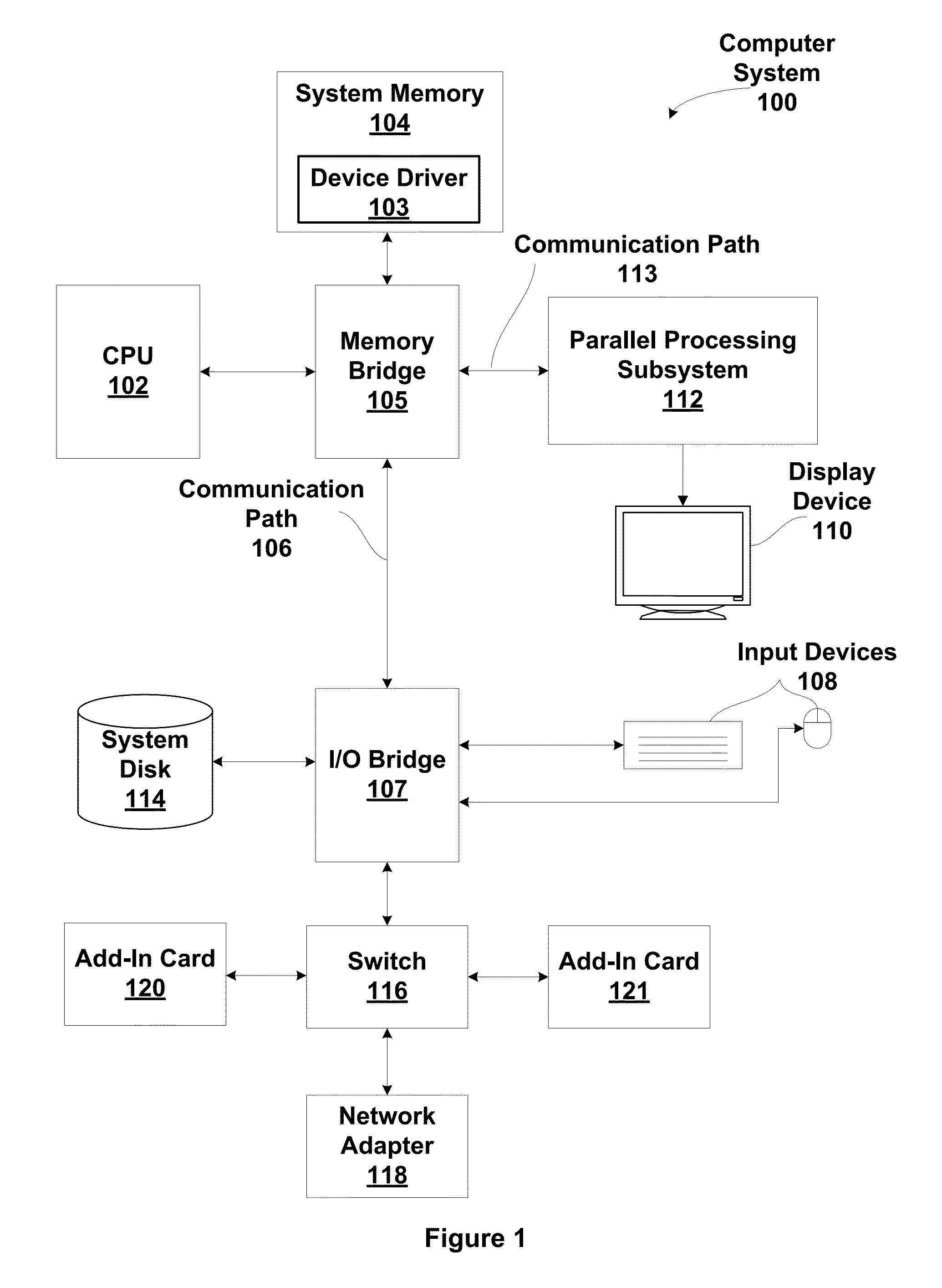
[0023]FIG. 2A is a block diagram illustrating a computer system 100 configured to implement one or more aspects of the present invention. Computer system 100 includes a central processing unit (CPU) 102 and a system memory 104 communicating via an interconnection path that may include a memory bridge 105. Memory bridge 105, which may be, e.g., a Northbridge chip, is connected via a bus or other communication path 106 (e.g., a HyperTransport link) to an I / O (input / output) bridge 107. I / O bridge 107, which may be, e.g., a Southbridge chip, receives user input from one or mo...


PUM


Abstract

One embodiment of the present invention sets forth multigrid generation technique which enables accurate simulations of large scale three dimensional (3D) fluid volumes. A model of the fluid to be simulated is represented using a cell grid. The generated multigrid provides a hierarchy of increasingly coarser representations of the model that are used by a pressure solver. Eulerian simulation techniques require solving a linear system to determine pressure values for each cell within the cell grid. Different levels of the multigrid are then used to compute the pressure values for different regions of the model, maintaining accuracy near the surface of the fluid while simplifying the computations. The accurate pressure values ensure that the simulation produces detailed features of the water movement. Additionally, the multigrid pressure solver may be optimized for execution by a graphics processor.

Description

CROSS-REFERENCE TO RELATED APPLICATIONS[0001]This application claims benefit of U.S. provisional patent application Ser. No. 61 / 515,286 (Attorney Docket No. NVDA / SC-10-0323-US0) filed Aug. 4, 2011, and titled “REAL-TIME EULERIAN WATER SIMULATION USING A RESTRICTED TALL CELL GRID.” The subject material of this related application is hereby incorporated herein by reference.FIELD OF THE INVENTION[0002]The present invention generally relates to free surface water simulation and more specifically to a multigrid pressure solver for fluid simulation.DESCRIPTION OF THE RELATED ART[0003]Grid-based (Eulerian) and particle-based (Lagrangian) simulation techniques are used to generate special effects involving fluids (liquids and gases) in feature films and commercials. Conventional techniques employed for free surface water simulations are limited to off-line computation due to the complexity of the models and the simulation performance needs. Real-time performance for free surface water simul...

Claims


Application Information

Patent Timeline
Patent Type & Authority Applications(United States)
IPC IPC(8): G06T15/00
CPCG06T13/60G06T17/20G06T2210/24A63F2300/663G06T13/80G06T17/00G06T1/60G06T13/20
Inventor CHENTANEZ, NUTTAPONGMULLER-FISCHER, MATTHIAS
Owner NVIDIA CORP
Learn More