Handy scanner apparatus and control method thereof

Inactive Publication Date: 2013-02-07
LEE MYOUNG SOOL
View PDF10 Cites 40 Cited by
  • Summary
  • Abstract
  • Description
  • Claims
  • Application Information

AI Technical Summary

Benefits of technology

[0035]The present invention simplifies scanning process in which the handheld scanner stitches tile images directly captured from the scanning part. The advantage thereof lies on enhanced precision of positioning pixels and increase in data processing speed, especially on industrial purposes.
[0036]In addition, the present invention is able to approximate the size of the window that performs scanning to that of the housing, maximizing the scanning area when there is a physical disturbance to the scanner.
[0037]Furthermore, the present invention is able to scan uneven surfaces, and the size of the scanner can be reduced by means of an acceleration

Problems solved by technology

Due to an excessive amount of generated data, this method may delay the process, limiting the precision when putting linear pixels together.
Furthermore, the scanner has a disadvantageous structure which often has a limit on the image size that can be scanned.
Thus, the space between the housing (20) and the contact line image sensor (30) does not allow scanning the underneath thereof when the handheld scanner (10) experiences a physical obstruction.
This crucial problem of the handheld scanner (10) frequently occurs, especially when scanning a book or a pile of documents which are well bound, thus contain uneven surfaces.
Any words left out from scanning may disturb understanding the entire context written on the object.
In addition, the limited depth of focus of the line image sensor (30) significantly lowers the quality of the scanning result eve

Method used


Image

  • Handy scanner apparatus and control method thereof
  • Handy scanner apparatus and control method thereof
  • Handy scanner apparatus and control method thereof

Examples


Embodiment Construction

[0055]All examples and conditional language recited herein are intended for pedagogical purposes to aid the reader in understanding the principles of the invention and the concepts contributed by the inventor to furthering the art, and are to be construed as being without limitation to such specifically recited examples and conditions, nor does the organization of such examples in the specification relate to a showing of the superiority and inferiority of the invention.

Although the embodiments of the present invention have been described in detail, it should be understood that the various changes, substitutions, and alterations could be made hereto without departing from the spirit and scope of the invention. In addition, any explanations or diagrams which may stray from the main idea of the invention are excluded to avoid unnecessary confusion.

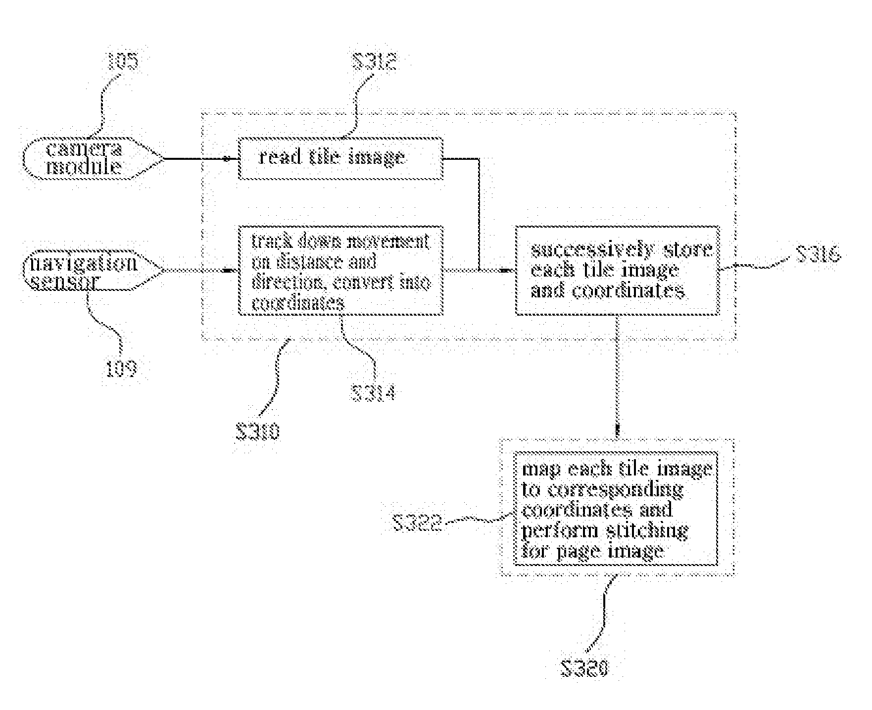
[0056]A digital camera captures an image by frame; a frame comprises an array of pixels in rows and columns; the vertical synchronization si...


PUM


Abstract

The present invention relates to a handy scanner apparatus and a control method thereof, which scan the surface of the object under scan, larger than a scanner, into units of two-dimensional tile images each of which has a predetermined size, and synthesize the photographed images in accordance with shift information into final page images. Particularly, a scan unit comprises: a transparent window portion which forms an area of tile images to be scanned; a housing portion which prevents the introduction of light from an external source; a camera module which maintains a fixed optical distance from the object under scan, and photographs tile images; a lighting module which provides light only during a preset time in accordance with a lighting signal; and a shift sensing module which outputs shift information. According to the present invention, the surface of the object under scan is scanned by units of two-dimensional tile images in which positions of pixels are physically fixed, to thereby achieve improved accuracy of positions of pixels. According to the present invention, the number of arithmetic operations required for image synthesis is reduced, thus enabling high speed signal processing, and the bottom surface of the housing portion can approach closely to the scanning area, thus maximizing a scannable area.

Description

TECHNICAL FIELD[0001]The present invention relates to a handy (or handheld) scanner, more particularly to a handy (or handheld) scanning device and the control method thereof when scanning an object of which surface is larger than the reading area of the scanner device.BACKGROUND ART[0002]A scanner is a device that optically scans any objects and converts the result into a digital image (collectively referred to as “scanner” hereinafter).A scanner reads an optical image on the surface of an object and converts it into a digital signal for storage or transmission. A scanner can have a wide range of uses in collaboration with digital image processing.[0003]One method commonly used to change an optical image to a digital signal is a linear array of numerous contact image sensors (CIS).[0004]There are two different types of movement sources of a scanner: motor-powered automatic scanners in which the scanning part is moved by an electric motor and manual scanners in which the scanning pa...

Claims


Application Information

Patent Timeline
IPC IPC(8): H04N5/225
CPCH04N1/107H04N2201/0414H04N2201/0471H04N2201/04734G06K7/10H04N1/00519H04N1/3876G06V30/142
Inventor LEE, MYOUNG SOOL
Owner LEE MYOUNG SOOL
Why Eureka
Try Eureka