
System, method and apparatus for increasing surface solar reflectance of roofing

a technology of surface solar reflectance and roof, which is applied in the field of roofs, can solve the problems of increasing the demand for indoor cooling energy, contributing to smog formation, and significant amounts of solar heat flux that can be absorbed by the surface with low solar reflectivity

Active Publication Date: 2013-02-07
CERTAINTEED CORP
View PDF4 Cites 17 Cited by
  • Summary
  • Abstract
  • Description
  • Claims
  • Application Information

AI Technical Summary

Benefits of technology

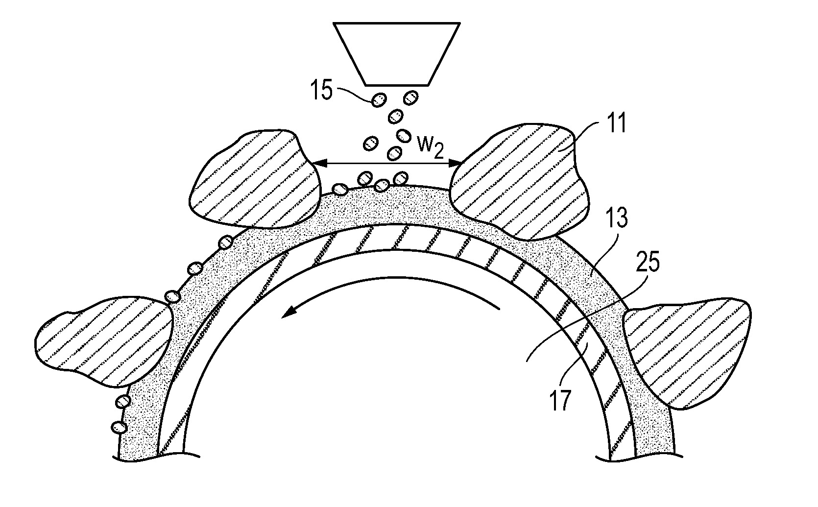
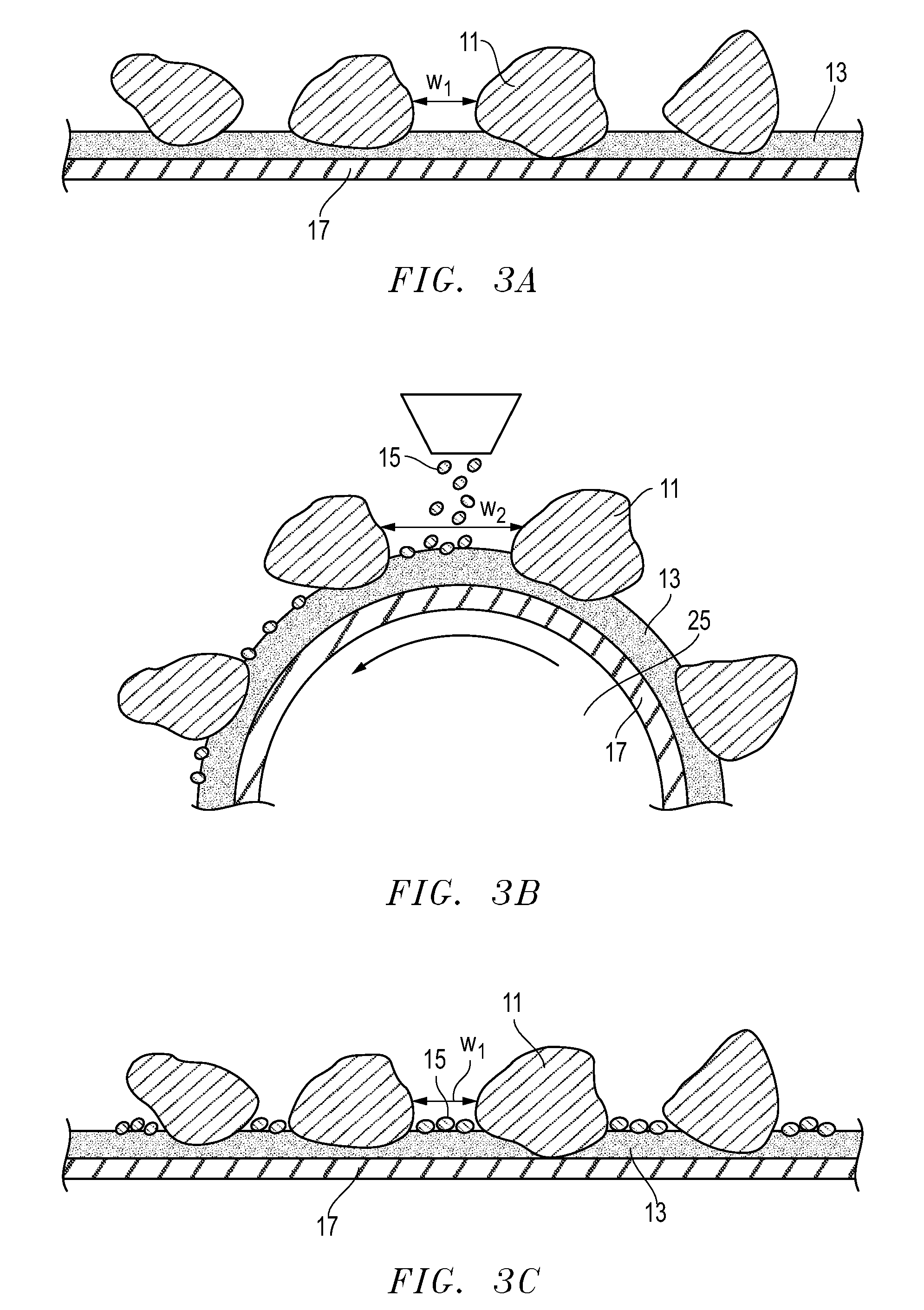
The patent describes a roofing product with solar reflective particles on the exposed binder layer, which enhance the reflective properties of the roof. The reflective particles are smaller in size than the roofing granules and have a high solar reflectance. The method of fabricating the roofing product involves coating a substrate with a binder layer, depositing roofing granules on the binder layer, and pressing the roofing granules into the binder layer to form a subassembly. The subassembly is then turned on a roller to space between the roofing granules and deposit reflective particles on the widened spaces. The technical effects of this invention include improved reflective properties, energy efficiency, and reduced heat absorption by the roof.

Problems solved by technology

As a result, significant amounts of solar heat flux can be absorbed due to those surfaces with low solar reflectivity, particularly on hot summer days.
This not only increases the demand for indoor cooling energy, but also contributes to smog formation due to higher surface temperatures.
However, such roofing granules and the resultant roofing membranes or asphalt shingles are known to have low solar reflectivity and hence will absorb solar heat especially through the near infrared range of the solar spectrum.

Method used


Image

  • System, method and apparatus for increasing surface solar reflectance of roofing
  • System, method and apparatus for increasing surface solar reflectance of roofing
  • System, method and apparatus for increasing surface solar reflectance of roofing

Examples


example 1

[0032]Samples of modified bitumen membrane (e.g., Flinlastic GTA cap sheet, available from CertainTeed Corp., Little Rock, Ark.) with Energy Star rated solar reflectance of 65% were filled with two types of reflective particles to cover the exposed asphalt between roofing granules. A bitumen membrane sample of size 12″×12″ was first heated in a forced-air oven to 80° C. to simulate the product temperature during the manufacturing of the membrane prior to press rolls. In one example, about 10 g of reflective particles of ceramic grog (e.g., 90A from Maryland Refractory, Irondale, Ohio) having solar reflectance >70%, and a size of passing #40 mesh were sprinkled onto the sheet, and then pressed by a 20 lb roller to press them into the gap in between the granules. The sample was then flipped over to remove excess particles. In the same manner, a second sample was prepared by filling the gaps with white colored quartz sand (e.g., SpectraQuartz available from Fairmount Minerals, Chardon,...

example 2

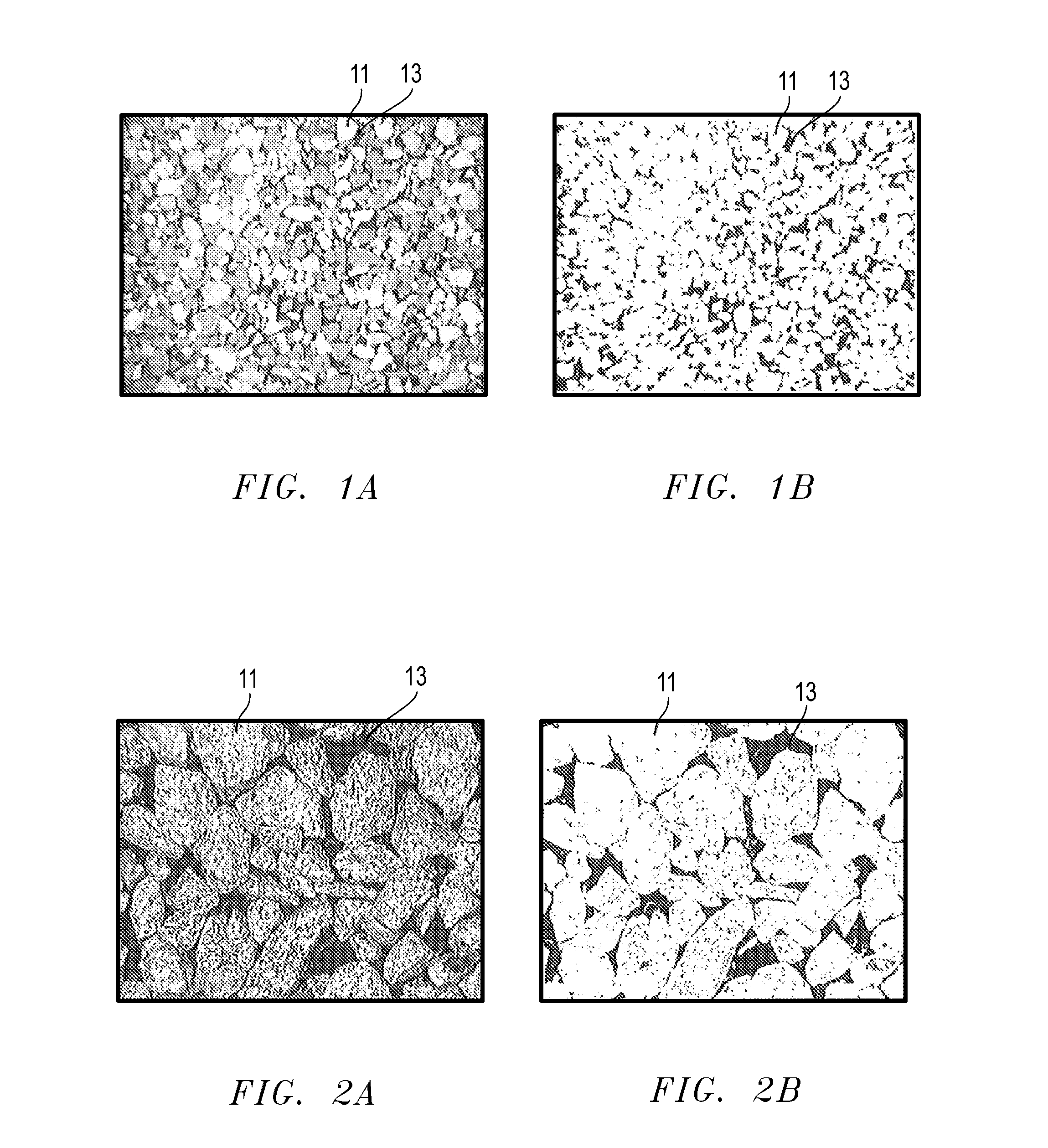
[0033]Roofing membranes with and without the reflective particles filling the gap between the granules were produced according to a typical roofing membrane manufacturing process. FIGS. 7 and 8 are side-by side photographs showing, on the left, conventional roofing products with no filling of reflective particles and, on the right, embodiments of a roofing product filled with reflective particles.

[0034]These roofing products were produced by coating a fiberglass mat with APP-modified asphalt and then roofing granules having a solar reflectance of 71% (measured by ASTM C1549 method) were deposited onto the molten asphalt running at a speed of 120 feet / minute. The resultant composite was then wound through a series of rollers to reclaim granules that were not embedded into the modified bitumen. The membrane was then cooled to a surface temperature of 160° F. prior to the application of a reflective filler. The reflective filler was of ceramic grog nature (available from CertainTeed Co...


PUM

PropertyMeasurementUnit
solar reflectanceaaaaaaaaaa

Abstract

A roofing product has a substrate having a binder layer and roofing granules on a majority of the binder layer, such that an exposed portion of the binder layer does not have the roofing granules. In addition, reflective particles may be located on the exposed portion of the binder layer. The reflective particles are smaller in size than the roofing granules, and the reflective particles have a solar reflectance of greater than 40%.

Description

[0001]This application claims priority to and the benefit of U.S. Prov. Pat. App. No. 61 / 515,391, filed Aug. 5, 2011, and is incorporated herein by reference in its entirety.BACKGROUND OF THE INVENTION[0002]1. Field of the Disclosure[0003]The present invention relates in general to roofing and, in particular, to a system, method and apparatus for increasing the surface solar reflectance of roofing shingles.[0004]2. Related Art[0005]It has been shown that surfaces of man-made structures, such as a roofing covering, cladding, or pavement surface, can absorb significant amounts of solar radiation. This causes the so-called “heat island effect,” where the temperatures in an urban area tend to be several degrees higher than surrounding areas. As a result, significant amounts of solar heat flux can be absorbed due to those surfaces with low solar reflectivity, particularly on hot summer days. This not only increases the demand for indoor cooling energy, but also contributes to smog format...

Claims


Application Information

Patent Timeline
Patent Type & Authority Applications(United States)
IPC IPC(8): E04D1/28B05D5/06B05D1/04B32B5/16
CPCB32B11/02Y10T428/24372B05D2252/02B05D2401/32B05D2451/00E04D5/12Y10T428/24405Y10T428/24413B32B5/16B32B27/308B32B27/36B32B27/38B32B27/40B32B2419/06Y02B80/34Y10T428/2443Y10T428/24421B05D2425/01Y02B80/00Y02A30/254
Inventor SHIAO, MING LIANGKALKANOGLU, HUSNU M.WATTMAN, GEORGE
Owner CERTAINTEED CORP
Learn More