Radiotherapy Apparatus

a technology of radiotherapy and apparatus, applied in the field of radiotherapy systems, can solve the problems of limiting the scope of substantial changes in the linac, increasing the treatment time, and undetectedly prolonging the treatment tim

Inactive Publication Date: 2013-02-07
ELEKTA AB
View PDF7 Cites 11 Cited by
  • Summary
  • Abstract
  • Description
  • Claims
  • Application Information

AI Technical Summary

Benefits of technology

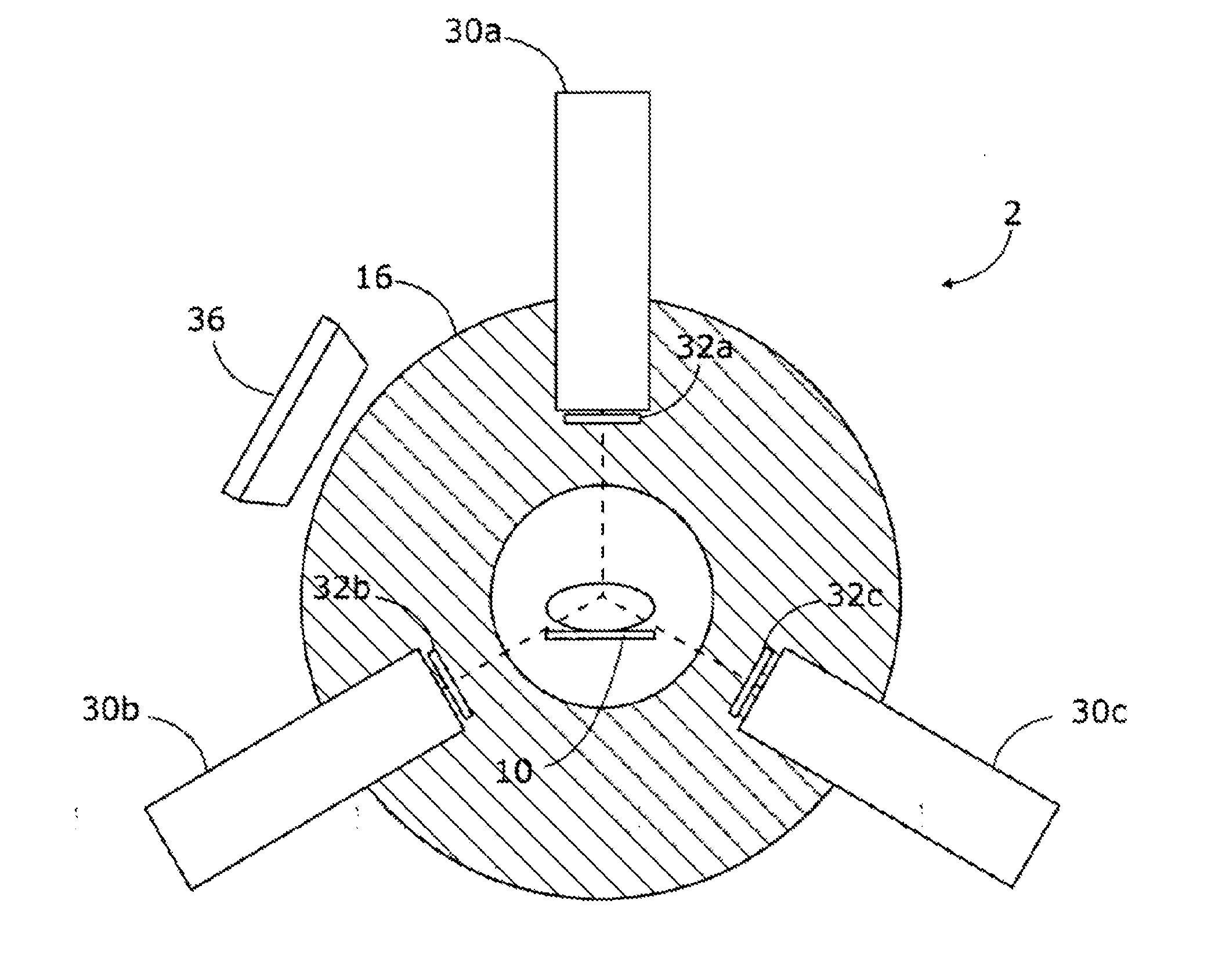
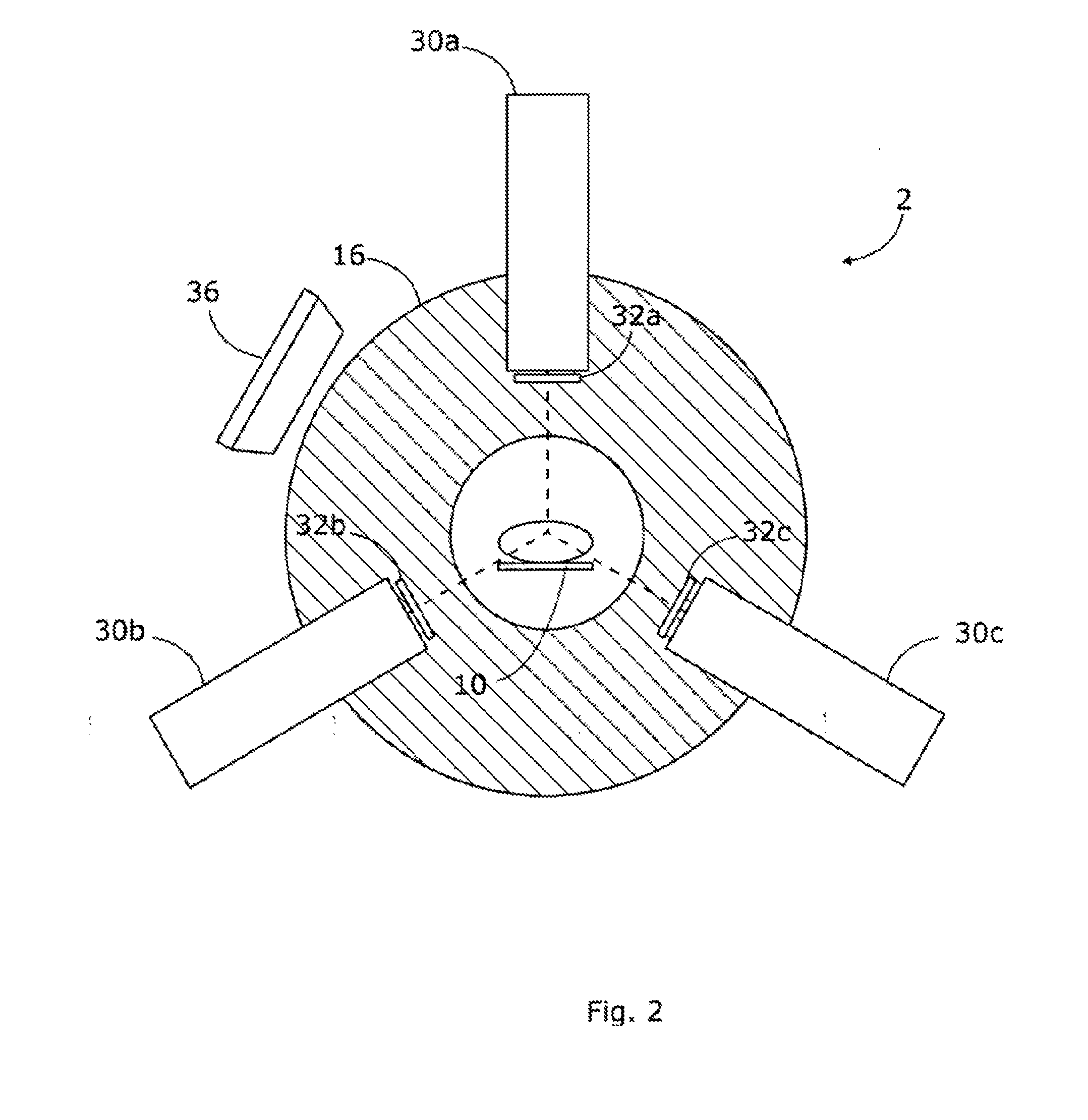
[0009]Further, in an existing linac-based radiotherapeutic apparatus, if a higher dose rate is required then this can be achieved straightforwardly by making appropriate changes to the single linac. In a combined MRI / linac device, there are additional constraints imposed by the need to package the linac so that it will remain compatible with the design of the MRI coils. This may limit the scope for making substantial changes to the linac. Meanwhile, there is adequate space around the MRI coils for two, three, four or more linacs which may be distributed around the circumference in order to provide a corresponding multiplication of the available dose rate without affecting the size or compatibility of the individual linacs.

Problems solved by technology

Both of these factors have the effect of lowering the maximum achievable dose rate, which in turn increases the treatment time.
Whilst these techniques allow for the delivery of complex and accurate dose distributions, they also undesirably extend the time to deliver treatment.
This may limit the scope for making substantial changes to the linac.

Method used


Image

  • Radiotherapy Apparatus
  • Radiotherapy Apparatus
  • Radiotherapy Apparatus

Examples


Embodiment Construction

[0016]FIG. 2 is a cross-section view of a system according to embodiments of the present invention, comprising a radiotherapy apparatus and a magnetic resonance imaging (MRI) apparatus. The radiotherapy apparatus 6 and MRI apparatus 4 are shown schematically in FIG. 3.

[0017]The system includes a couch 10, for supporting a patient in the apparatus. The couch 10 is movable along a horizontal, translation axis (into the page of FIG. 2), such that a patient resting on the couch is moved into the radiotherapy and MRI apparatus. In one embodiment, the couch 10 is rotatable around a central vertical axis of rotation, transverse to the translation axis, although this is not illustrated. The couch 10 may form a cantilever section that projects away from a support structure (not illustrated). In one embodiment, the couch 10 is moved along the translation axis relative to the support structure in order to form the cantilever section, i.e. the cantilever section increases in length as the couch...


PUM


Abstract

A radiotherapy apparatus is described which includes a patient support, a magnetic resonance imaging (MRI) apparatus for obtaining imaging data of a patient positioned on the patient support, and multiple linear accelerators, each aligned in a plane transverse to the patient support and arranged to provide a therapeutic beam of x-ray radiation to the patient.

Description

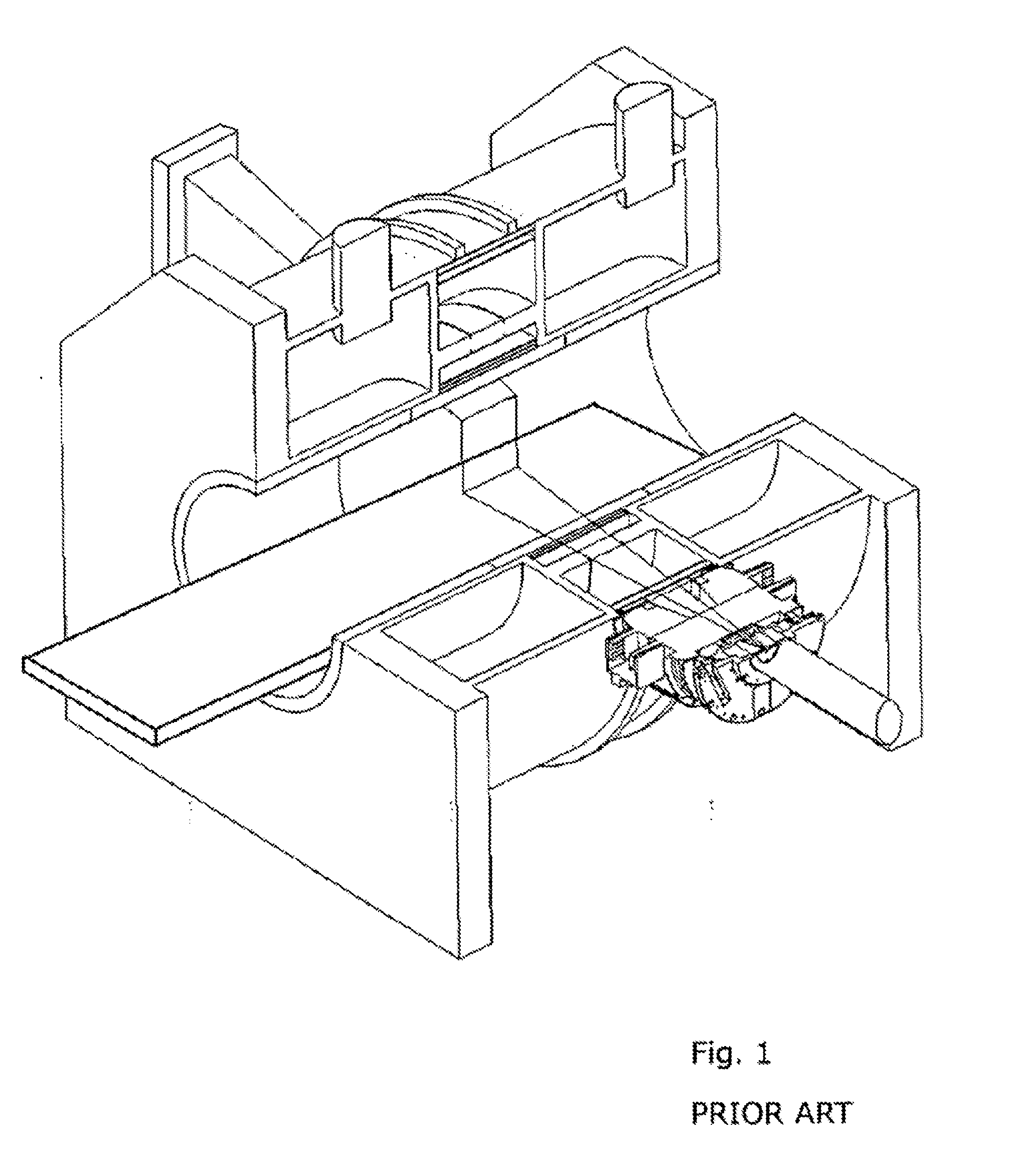
[0001]This Application is a continuation of Patent Cooperation Treat Patent Application PCT / EP2010 / 002324 filed Apr. 15, 2010, which is incorporated herein by reference.TECHNICAL FIELD[0002]The present invention relates to radiotherapy systems, and particularly to radiotherapy systems comprising integrated magnetic resonance imaging apparatus.BACKGROUND ART[0003]Current designs for combining magnetic resonance imaging (MRI) with radiotherapy apparatus in the form of a linear accelerator (linacs) involve arranging the magnetic field coils to allow a linac to be placed in such a way as to minimize the effect of the magnetic field on its operation, and allow the treatment beam to penetrate to the patient's target region with minimal attenuation. Such a design is shown in FIG. 1.[0004]In current designs the radiation beam has to pass through the MRI magnet and RF coils, thereby attenuating the beam. For this reason, the linac also needs to be placed at an extended distance from the pati...

Claims


Application Information

Patent Timeline
Patent Type & Authority Applications(United States)
IPC IPC(8): A61N5/10A61B6/00A61B5/055
CPCA61N5/1067A61N5/1081A61N5/1084A61N2005/1055A61N2005/1061
Inventor LAGENDIJK, JANJAFFRAY, DAVID
Owner ELEKTA AB
Why Eureka
Try Eureka