Reinforced longitudinal beam for a railway vehicle

Inactive Publication Date: 2013-02-14
SIEMENS MOBILITY AUSTRIA GMBH
View PDF9 Cites 6 Cited by
  • Summary
  • Abstract
  • Description
  • Claims
  • Application Information

AI Technical Summary

Problems solved by technology

However, the welded seams between the substructure and the side walls or between the side walls and the roof inside the wagon body are only access

Method used


Image

  • Reinforced longitudinal beam for a railway vehicle
  • Reinforced longitudinal beam for a railway vehicle
  • Reinforced longitudinal beam for a railway vehicle

Examples


Embodiment Construction

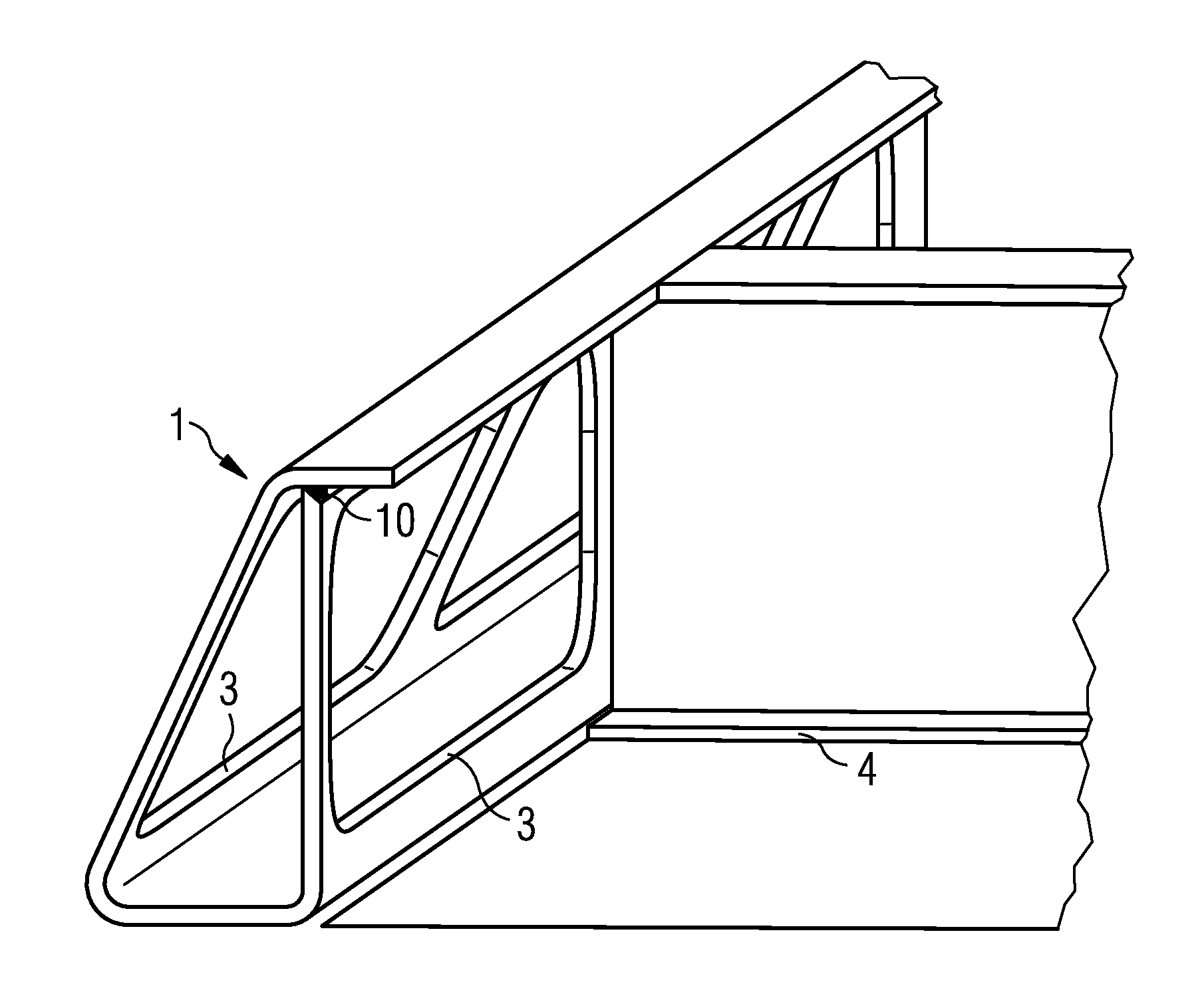
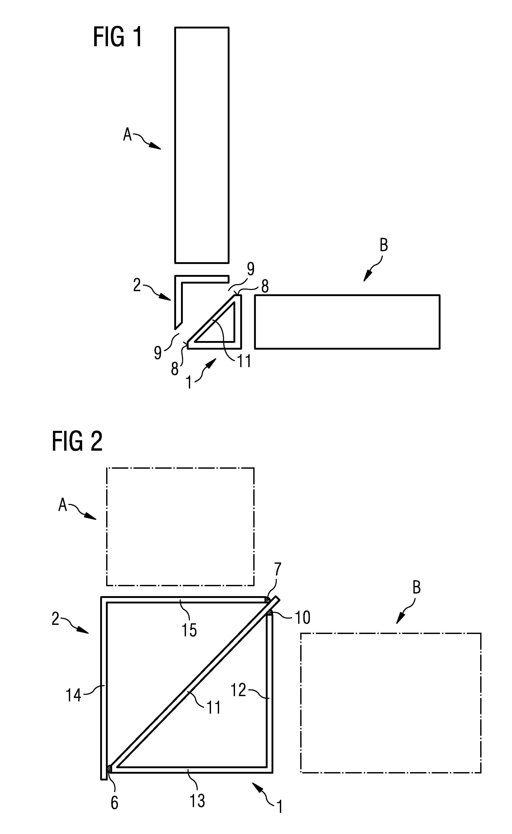
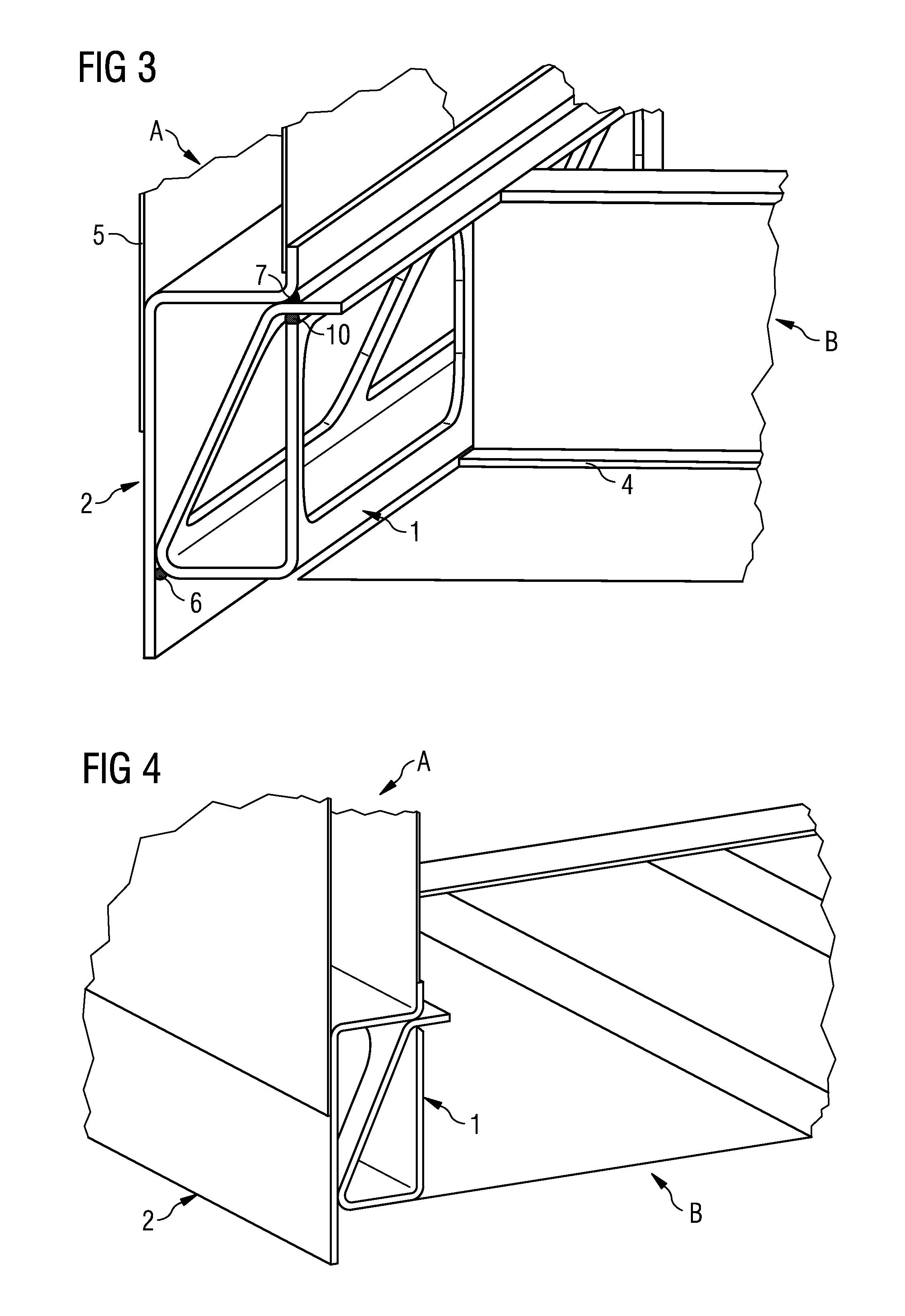
[0005]An object is to specify a longitudinal beam for railway vehicles which permits the automated welding of the connection points between the major components (substructure, side walls, roof) of a railway vehicle, wherein the longitudinal beam is so strong that the penetration of the longitudinal beam by the cross-members of the substructure can be omitted.

[0006]The object is achieved by a longitudinal beam as claimed in the independent claim. Advantageous embodiments are the subject of subordinate claims.

[0007]According to the fundamental idea of the invention, a longitudinal beam is constructed for railway vehicles, which is divided in the longitudinal axis into a first partial beam and a second partial beam, wherein in each case a partial beam is fastened to a major component (substructure, side walls, floor) assigned to this partial beam. Both the partial beams are designed in such a way that they can be combined to form a longitudinal beam and can be connected to each other b...


PUM


Abstract

A reinforced longitudinal beam for railway vehicles includes a first partial beam and a second partial beam. The first partial beam is connected to a second assembly of the railway vehicle and the second partial beam is connected to a first assembly of the railway vehicle. Particular surfaces are provided on the first partial beam for forming a welded connection to the second partial beam, and particular surfaces are provided on the second partial beam for forming a welded connection to the first partial beam, wherein one of the partial beams comprises an end facing.

Description

CROSS REFERENCE TO RELATED APPLICATIONS[0001]This application is the US National Stage of International Application No. PCT / EP2011 / 055745 filed Apr. 13, 2011, and claims the benefit thereof. The International Application claims the benefits of Austrian Application No. A 686 / 2010 AT filed Apr. 26, 2010. All of the applications are incorporated by reference herein in their entirety.FIELD OF INVENTION[0002]The invention relates to a reinforced longitudinal beam for a railway vehicle and a railway vehicle with such a longitudinal beam.BACKGROUND OF INVENTION[0003]Today railway vehicles, in particular passenger vehicles, are in practice only constructed as self-supporting metal structures. A vehicle body comprising a substructure, side walls, end walls and a roof is constructed. The substructure must withstand operating forces, in particular loading, clutch pressure and tensile forces. For this reason the substructure is frequently designed as a frame and usually comprises two external l...

Claims


Application Information

Patent Timeline
IPC IPC(8): B61D17/08B61D17/12B61D17/00
CPCB61D17/043
Inventor NEDELIK, ROBERT
Owner SIEMENS MOBILITY AUSTRIA GMBH
Why Eureka
Try Eureka