
Permanent magnet rotor

a permanent magnet rotor and rotor core technology, applied in the direction of magnetic circuit rotating parts, dynamo-electric machines, magnetic circuit shape/form/construction, etc., can solve the problems of large magnetic leakage of the rotor core, high torque ripple, and distorted top waveform of counter-electromotive force, etc., to achieve low magnetic leakage and torque ripple, simple structure, and high service performance

Inactive Publication Date: 2013-02-14
ZHONGSHAN BROAD OCEAN MOTOR MFG
View PDF19 Cites 27 Cited by
  • Summary
  • Abstract
  • Description
  • Claims
  • Application Information

AI Technical Summary

Benefits of technology

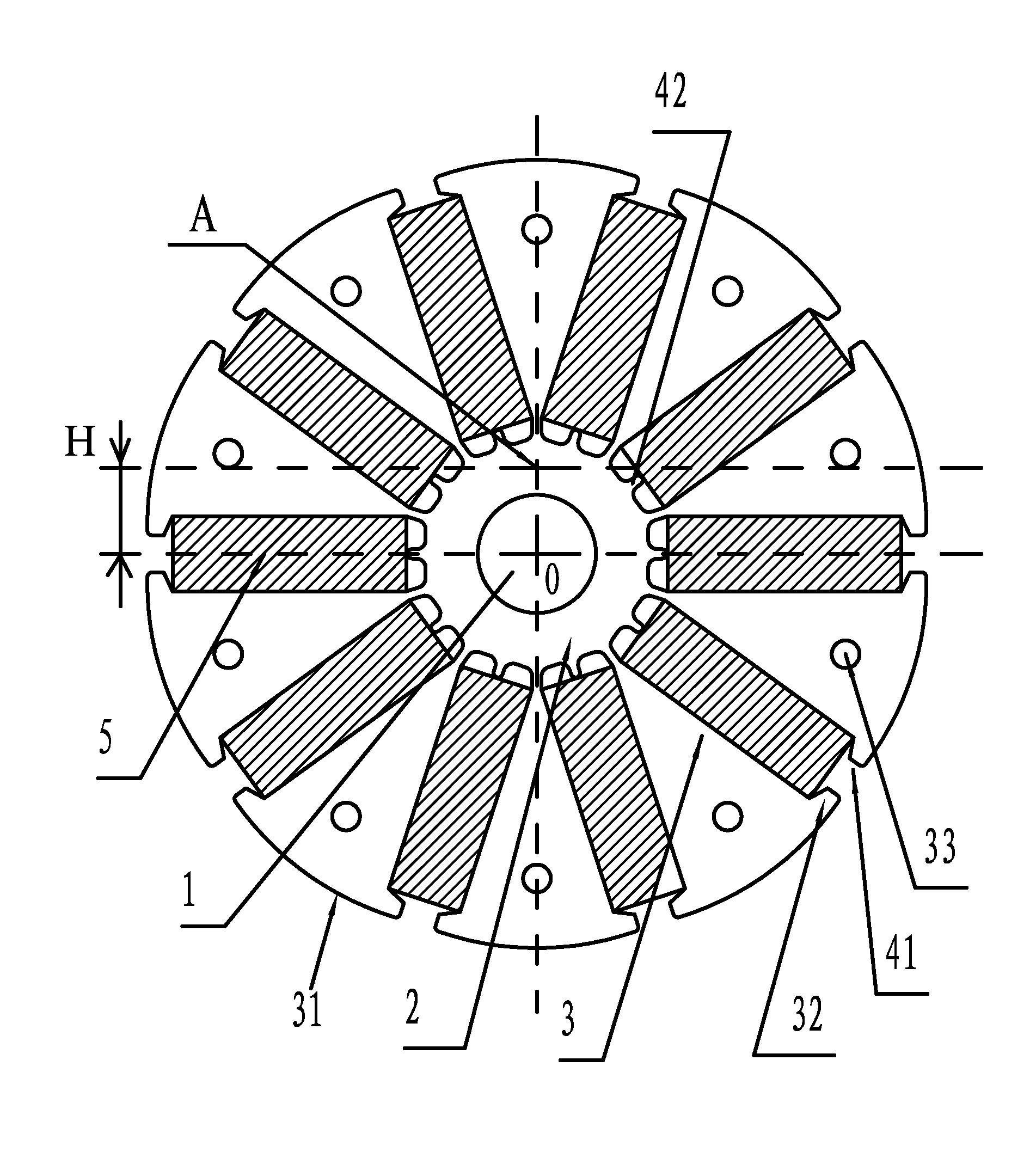
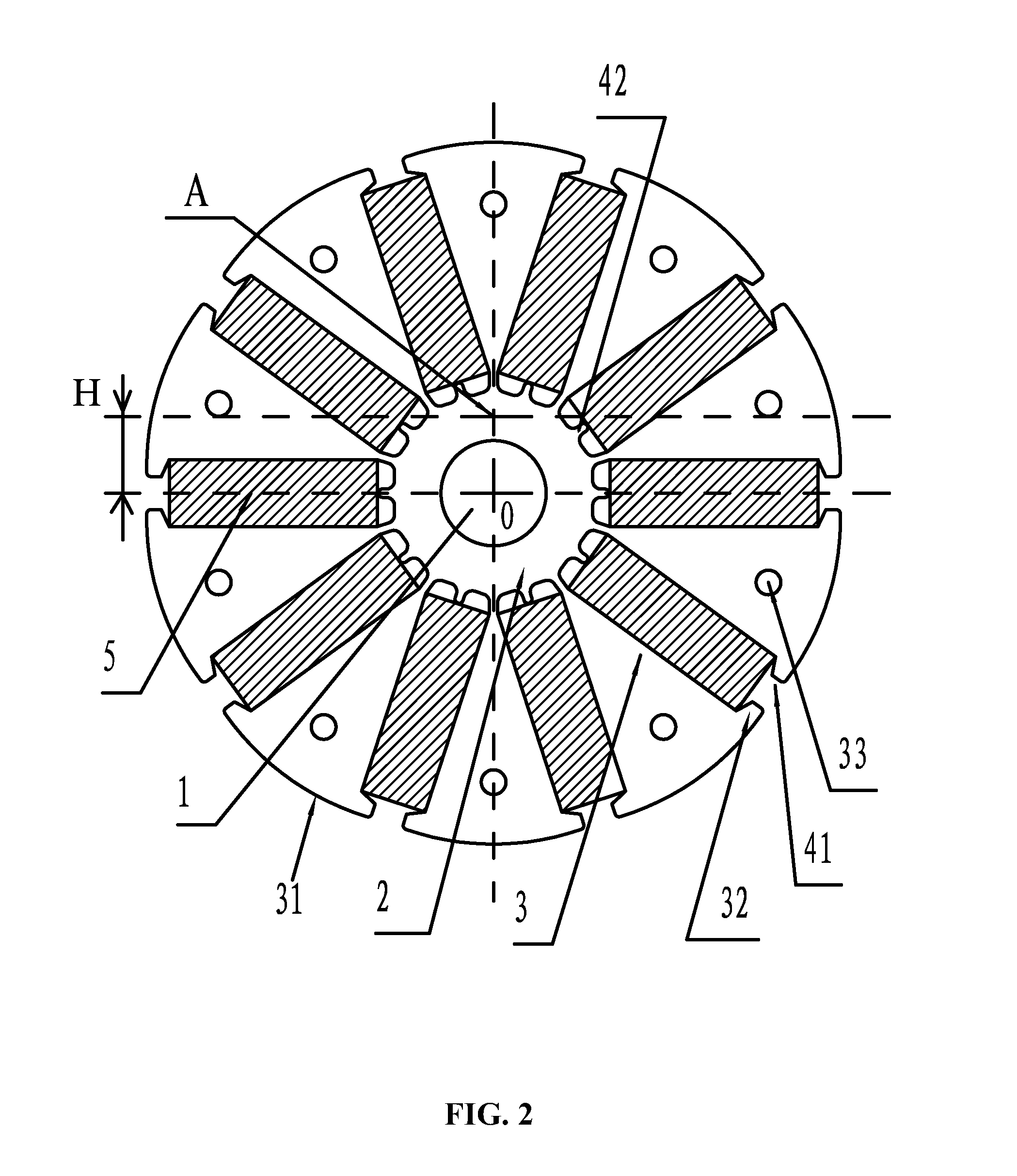
The patent aims to provide a permanent magnet rotor for a motor that has a simple structure, low magnetic leakage and torque ripple, big counter-electromotive force constant, smooth waveform of counter-electromotive force, high service performance, and low loss. This is achieved by designing the iron core with an annular ring having a central axial bore and a plurality of magnetic induction blocks protruding outwards from the outer side of the annular ring. The magnetic induction blocks at both sides of the opening of the radial recess protrude with a hook block, and the section of the outer side surface of the magnetic induction blocks is an circular-arc line and the outer side employs a point with a distance deviating from the center of the central axial bore as the center of circle. This helps to reduce magnetic leakage of the rotor core, lower cogging torque ripple, and achieve a big counter-electromotive force constant and smooth waveform of the counter-electromotive force. The distance between the two hook blocks arranged at the opening of the same radial recess is 3.5-5 mm, and a convex plate is arranged at the middle bottom of the radial recess, which further reduces magnetic leakage of the rotor core.

Problems solved by technology

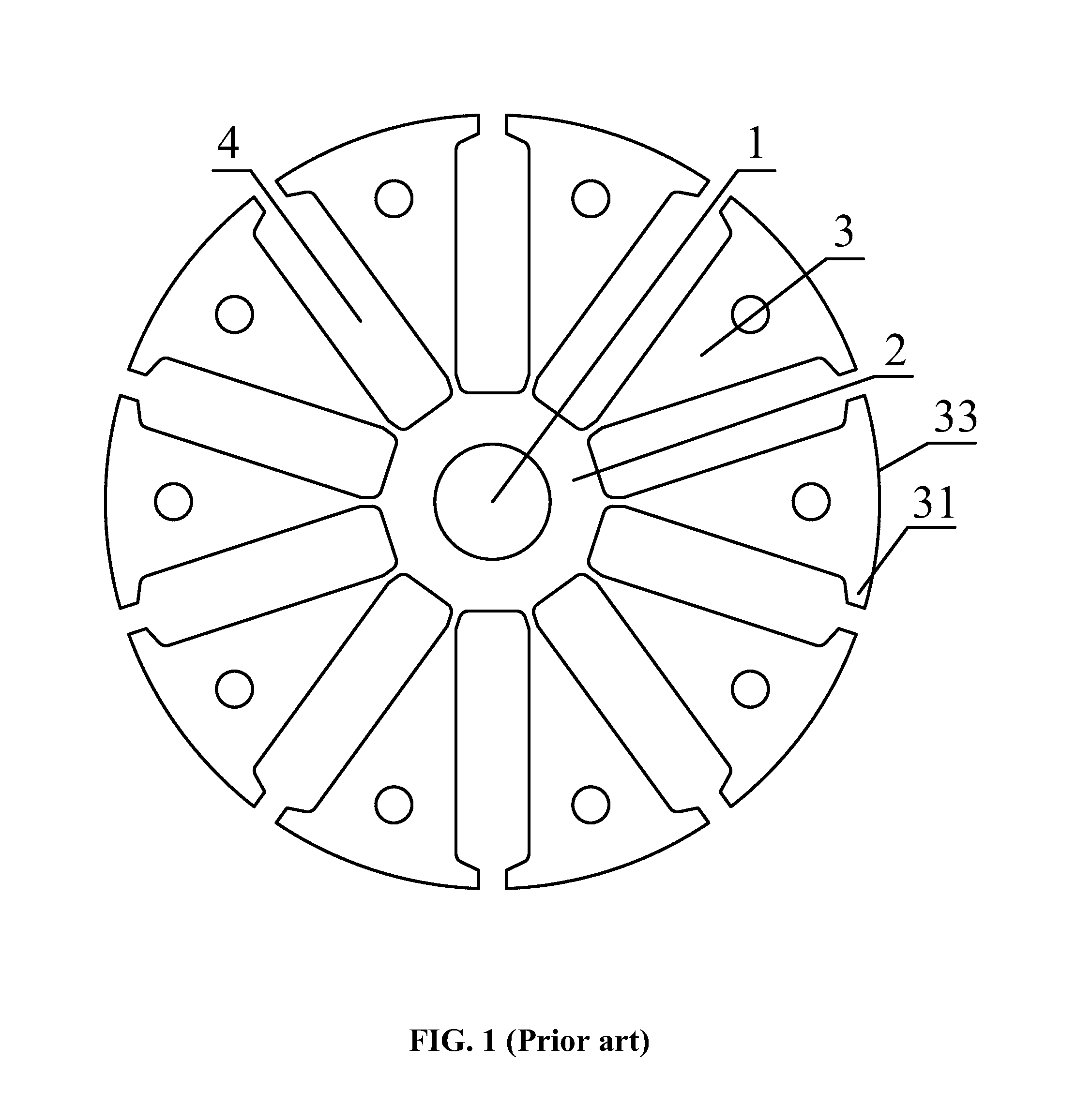
Such structure has the disadvantage of large magnetic leakage of the rotor core, high torque ripple, and distorted top waveform of counter-electromotive force.

Method used


Image

  • Permanent magnet rotor
  • Permanent magnet rotor
  • Permanent magnet rotor

Examples


Embodiment Construction

[0022]The invention is explained in further detail below with reference to the accompanying drawings and embodiments.

[0023]As shown in FIGS. 2, 3, and 4, a permanent magnet rotor of a motor comprises an iron core and a permanent magnet 5. The iron core comprises an annular ring 2 having a central axial bore 1 and a plurality of magnetic induction blocks 3 protruding outwards from an outer side of the annular ring 2. Between two adjacent magnetic induction blocks 3 form a radial recess 4 for mounting a permanent magnet 6. The magnetic induction blocks 3 at both sides of an opening 41 of the radial recess 4 protrude with a hook block 32. The section of the outer side surface 31 of the magnetic induction blocks 3 is an circular-arc line and the outer side surface 31 employs a point A with a distance H deviating from the center O of the central axial bore 1 as a center of circle. The distance H deviating from the center O of the central axial bore 1 is 5-20 mm The maximum external diame...


PUM


Abstract

A permanent magnet rotor for a motor, the permanent magnet rotor including an iron core and a permanent magnet. The iron core includes an annular ring having a central axial bore and a plurality of magnetic induction blocks protruding outwards from an outer side of the annular ring. Between two adjacent magnetic induction blocks form a radial recess for mounting the permanent magnets. The magnetic induction blocks at both sides of an opening of the radial recess protrude with a hook block. The section of an outer side surface of the magnetic induction blocks is a circular-arc line and the outer side surface employs a point with a distance deviating from the center of the central axial bore as a center of circle. The permanent magnet rotor has a simple structure, low magnetic leakage and torque ripple, big counter-electromotive force constant, and smooth waveform of counter-electromotive force.

Description

CROSS-REFERENCE TO RELATED APPLICATIONS[0001]Pursuant to 35 U.S.C. § 119 and the Paris Convention Treaty, this application claims the benefit of Chinese Patent Application No. 201120290991.3, filed Aug. 11, 2011, the contents of which are incorporated herein by reference.BACKGROUND OF THE INVENTION[0002]1. Field of the Invention[0003]The invention relates to a permanent magnet rotor of a motor.[0004]2. Description of the Related Art[0005]As shown in FIG. 1, a conventional permanent magnet rotor of a motor includes an annular ring 2 having a central axial bore 1 and a plurality of magnetic induction blocks 3 protruding outwards from an outer side of the annular ring 2. Between two adjacent magnetic induction blocks 3 form a recess 4 for mounting the permanent magnets 3. The magnetic induction blocks 3 at both sides of an opening of the recess 4 protrude with a hook block 31. An outer contour of the magnetic induction blocks 3 is formed by a circular-arc line 33 and the circular-arc l...

Claims


Application Information

Patent Timeline
IPC IPC(8): H02K1/27
CPCH02K2213/03H02K1/2773
Inventor PAN, MINGPAN
Owner ZHONGSHAN BROAD OCEAN MOTOR MFG
Learn More