
Color augmented local area contrast enhancement

a local area contrast and enhancement technology, applied in image enhancement, instruments, television systems, etc., can solve the problems of loss of relative thermal information across the entire image as represented by individual pixel values, loss of relative thermal information, and inability to discriminate discrimination ability in lace imagery, etc., to achieve the effect of enhancing the contrast of the imag

Active Publication Date: 2013-02-14
BAE SYST INFORMATION & ELECTRONICS SYST INTERGRATION INC
View PDF7 Cites 7 Cited by
  • Summary
  • Abstract
  • Description
  • Claims
  • Application Information

AI Technical Summary

Benefits of technology

The present invention provides a system and method for enhancing the contrast of an image through a local area contrast enhancement process. The system includes a color visual display and an image processor with two channels that map focal plane pixel values to different visual parameters, such as color, luminance, and saturation. The system can also combine a locally contrast enhanced product with a mapped product of a different visual channel. The method involves generating a first copy of an image, processing it to enhance visual contrast, generating a second copy of the image, processing it to provide at least one visual cue to radiant flux incident on the focal plane pixels within the image, and displaying a combined image formed from the combination of the locally enhanced first copy and the flux mapped second copy. The system and method can also adjust the display pixel intensity based on values of neighboring focal plane pixels and use a look up table to correlate the focal plane pixel value to predefined ratios of the intensities of sub pixels within the display pixel. The technical effects of the invention include improved image quality and better visual contrast.

Problems solved by technology

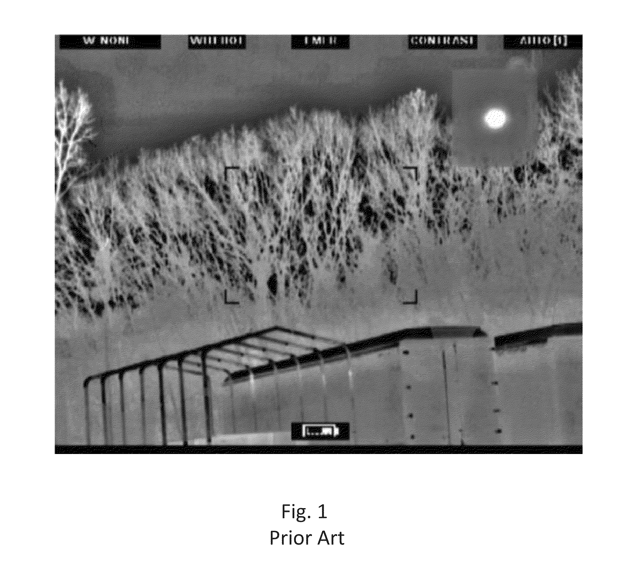
A potential detriment of this approach is that relative temperature information across the entire image as represented by individual pixel values is lost as a result of the local adjustment of these pixel values necessary to optimize contrast.
This loss of relative thermal information can be problematic in certain applications where a need to discriminate objects based on relative temperature exists (e.g. identifying the hot objects in an image).
This discrimination ability may be compromised in LACE imagery.
As a consequence, the relationship between pixel value and temperature otherwise inherent in thermal imagery is lost.
This loss of relative temperature information is a fundamental detriment in applications where object discrimination based on temperature is important.

Method used


Image

  • Color augmented local area contrast enhancement
  • Color augmented local area contrast enhancement
  • Color augmented local area contrast enhancement

Examples


Embodiment Construction

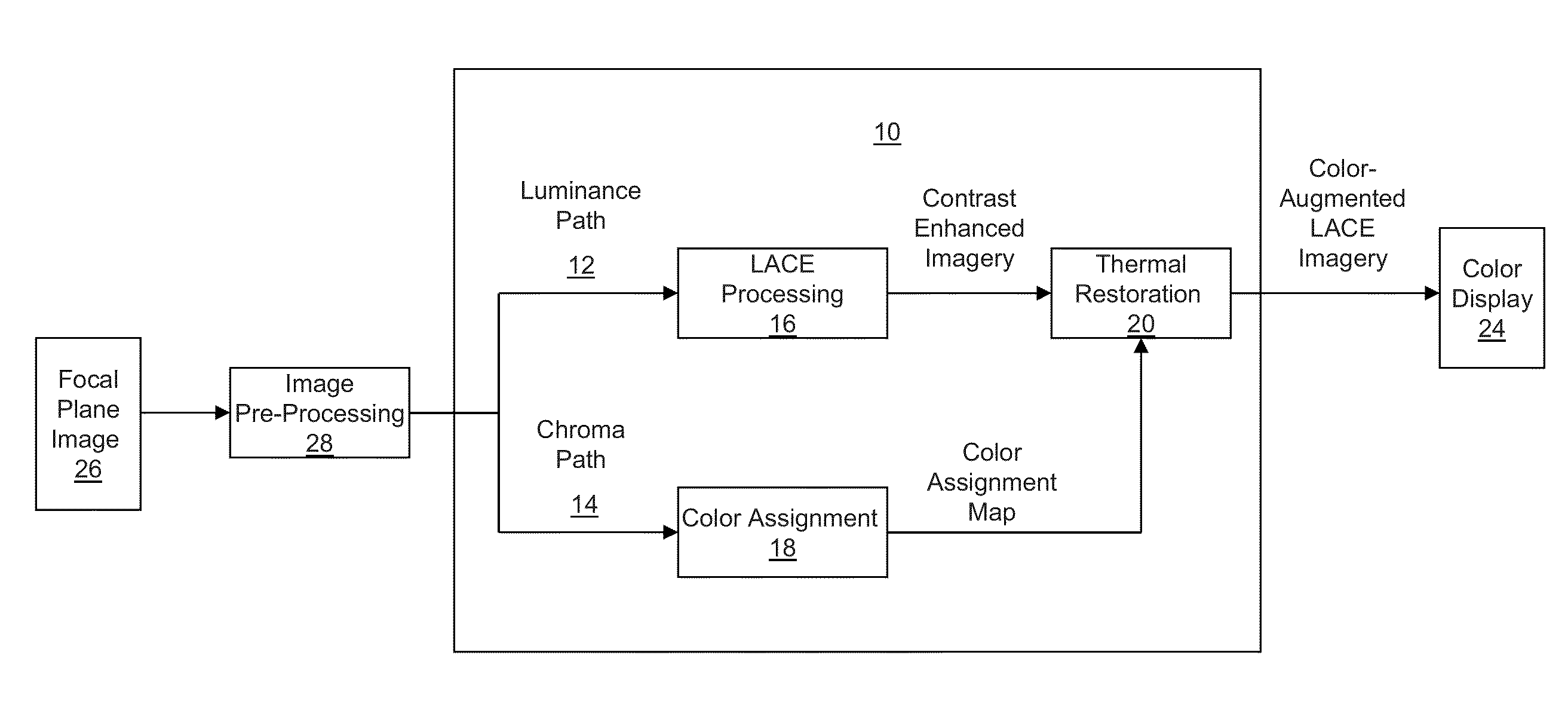
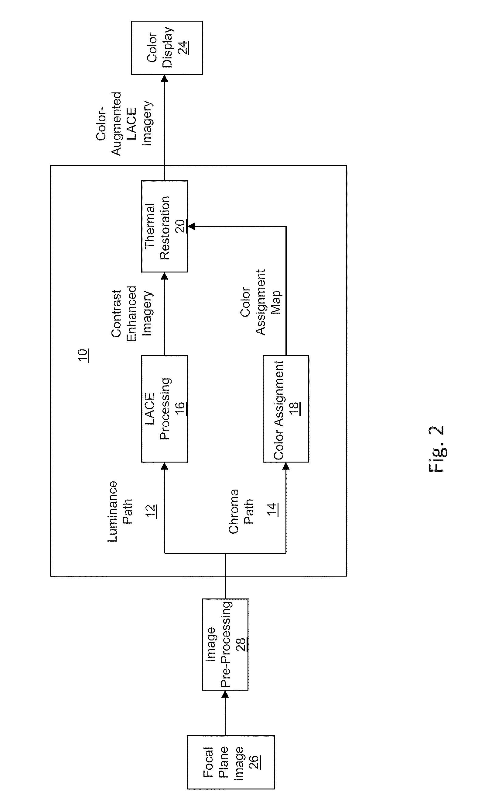
[0032]A method, as illustrated in FIG. 2 of preserving the relative temperature information of pixel values across an image, while also realizing the benefits of a LACE-enhanced image is disclosed. Specifically, the ability to discriminate hot from cold pixels in a consistent manner across an image is preserved while also enhancing the ability to discern detail in an image.

[0033]Relative temperature differences in a scene can be restored through use of color to display thermal imagery. In the proposed method 10, an input image is processed in two parallel paths, luminance 12 and chroma 14, and subsequently combined to perform this restoration. In one embodiment, image processing along the luminance path 12 involves applying a LACE algorithm to to the input image image 16 to modify pixel intensity values as necessary to improve contrast in the image. Image processing along the chroma path 14 involves applying the input image to a color assignment algorithm 18, whereby individual pixe...


PUM


Abstract

A method and system for color enabled local area contrast enhancement, are provided by generating a first copy of an image; processing the first copy to locally enhance visual contrast in the image; generating a second copy of the image; processing the second copy of the image to provide at least one visual cue to radiant flux within the image incident on the focal plane pixels; displaying a combined image formed from the combination of the locally enhanced first copy and flux mapped the second copy.

Description

RELATED APPLICATIONS[0001]This application claims the benefit of U. S. Provisional Application No. 61 / 522744, filed Aug. 12, 2012. This application is herein incorporated by reference in its entirety for all purposes.FIELD OF THE INVENTION[0002]The present invention relates to imaging, more particularly to creating color augmented, enhanced-contrast images.BACKGROUND OF THE INVENTION[0003]Local area contrast enhancement (LACE) algorithms are employed in thermal imaging applications to improve local contrast in a scene, whereby the image contrast of each region is locally optimized. A potential detriment of this approach is that relative temperature information across the entire image as represented by individual pixel values is lost as a result of the local adjustment of these pixel values necessary to optimize contrast. Thus, objects of the same temperature in different regions of the image may have different pixel values; conversely, objects of different temperatures may appear to...

Claims


Application Information

Patent Timeline
IPC IPC(8): G09G5/02
CPCG09G5/02G06T2207/10024G06T2207/20221H04N9/646G06T5/90H04N23/23H04N5/33
Inventor FEDA, FRANCIS M.
Owner BAE SYST INFORMATION & ELECTRONICS SYST INTERGRATION INC
Learn More