Plasma Booster for Plasma Treatment Installation

Active Publication Date: 2013-02-14
OERLIKON SURFACE SOLUTIONS AG PFAFFIKON
View PDF8 Cites 16 Cited by
  • Summary
  • Abstract
  • Description
  • Claims
  • Application Information

AI Technical Summary

Benefits of technology

[0031]One aim of the present invention, in contrast, is providing a plasma booster which avoids the disadvantageous effects of a hollow cathode and increases the plasma density within and outside of the plasma booster to such a degree that it contributes to the improvement of the treatment process. The plasma density in the interior is here significantly higher, which is of advantage for better dissociation or excitation, respectively, of gaseous precursors.
of a hollow cathode and increases the plasma density within and outside of the plasma booster to such a degree that it contributes to the improvement of the treatment process. The plasma density in the interior is here significantly higher, which is of advantage for better dissociation or excitation, respectively, of gaseous precursors.

Problems solved by technology

While having a locally restricted yet very high density, these secondary plasmas interfere with the planned plasma process through different effects such as overheating of individual substrates, plasma fluctuations, graphitization in the gas phase and others.

Method used


Image

  • Plasma Booster for Plasma Treatment Installation
  • Plasma Booster for Plasma Treatment Installation
  • Plasma Booster for Plasma Treatment Installation

Examples


example 1

[0047]Here the workpieces are charged according to prior art onto trees such that a hollow cathode is avoided. The substrate current in the process is low, the coating rate is low.

example 2

[0048]Here the pieces are charged onto trees which correspond to an arrangement according to the invention. When an IF bias is impressed a hollow cathode is thereby ignited and an increase of the substrate current as well as an increased deposition rate compared to Example 1. The geometric parameters of the hollow discharge were so adapted to the process parameters that the pieces were neither overheated nor the layer quality negatively affected.

example 3

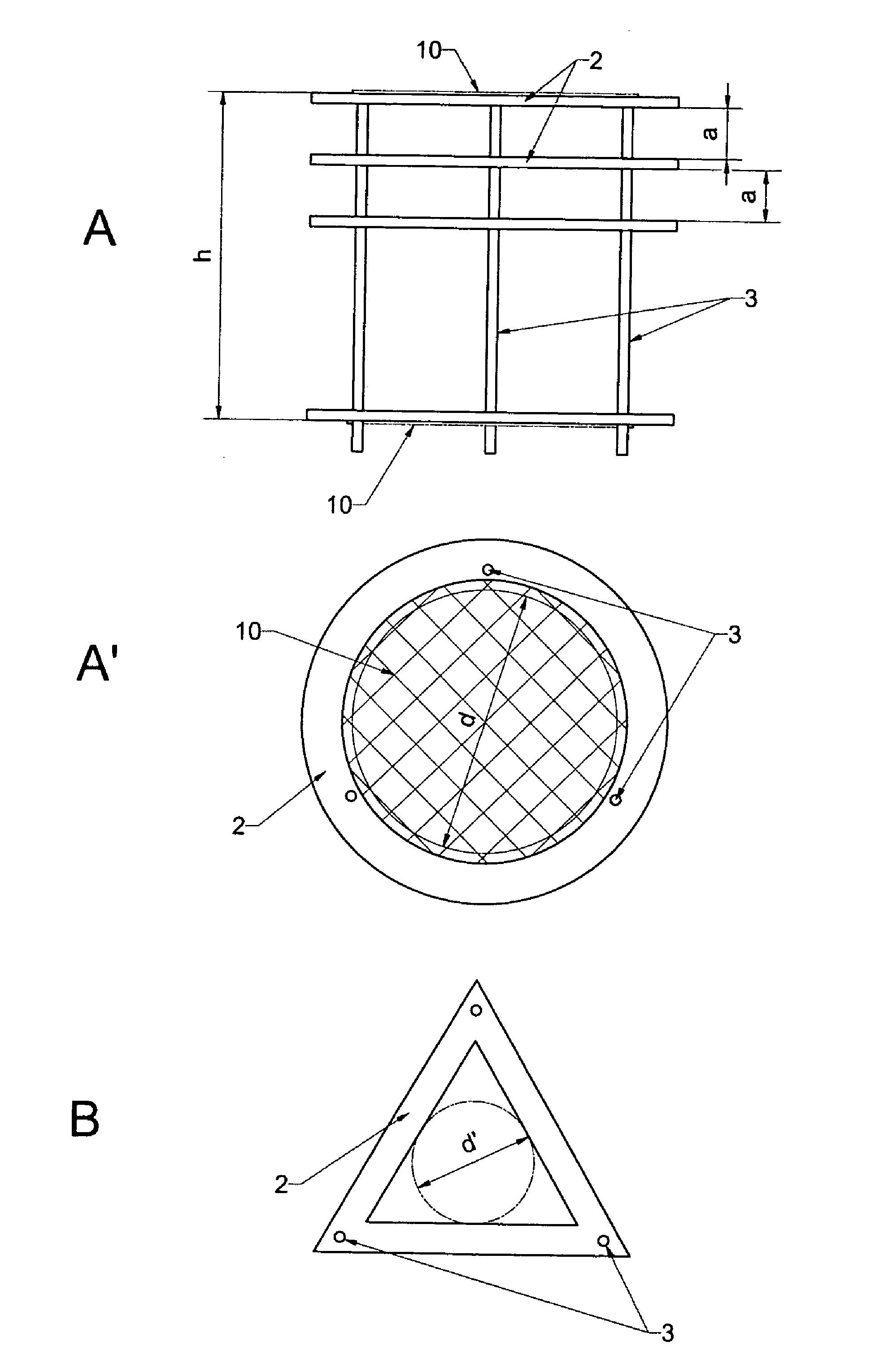
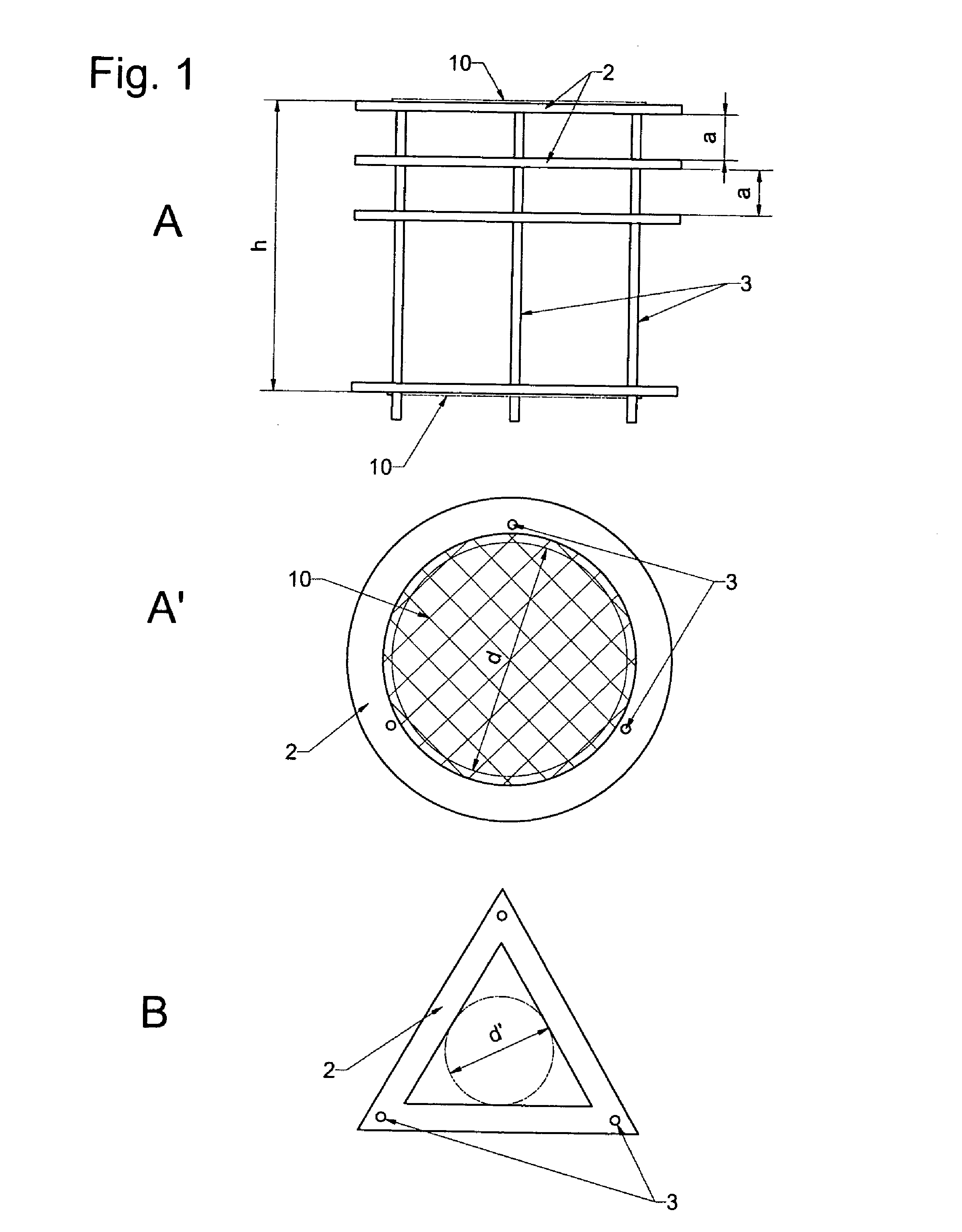
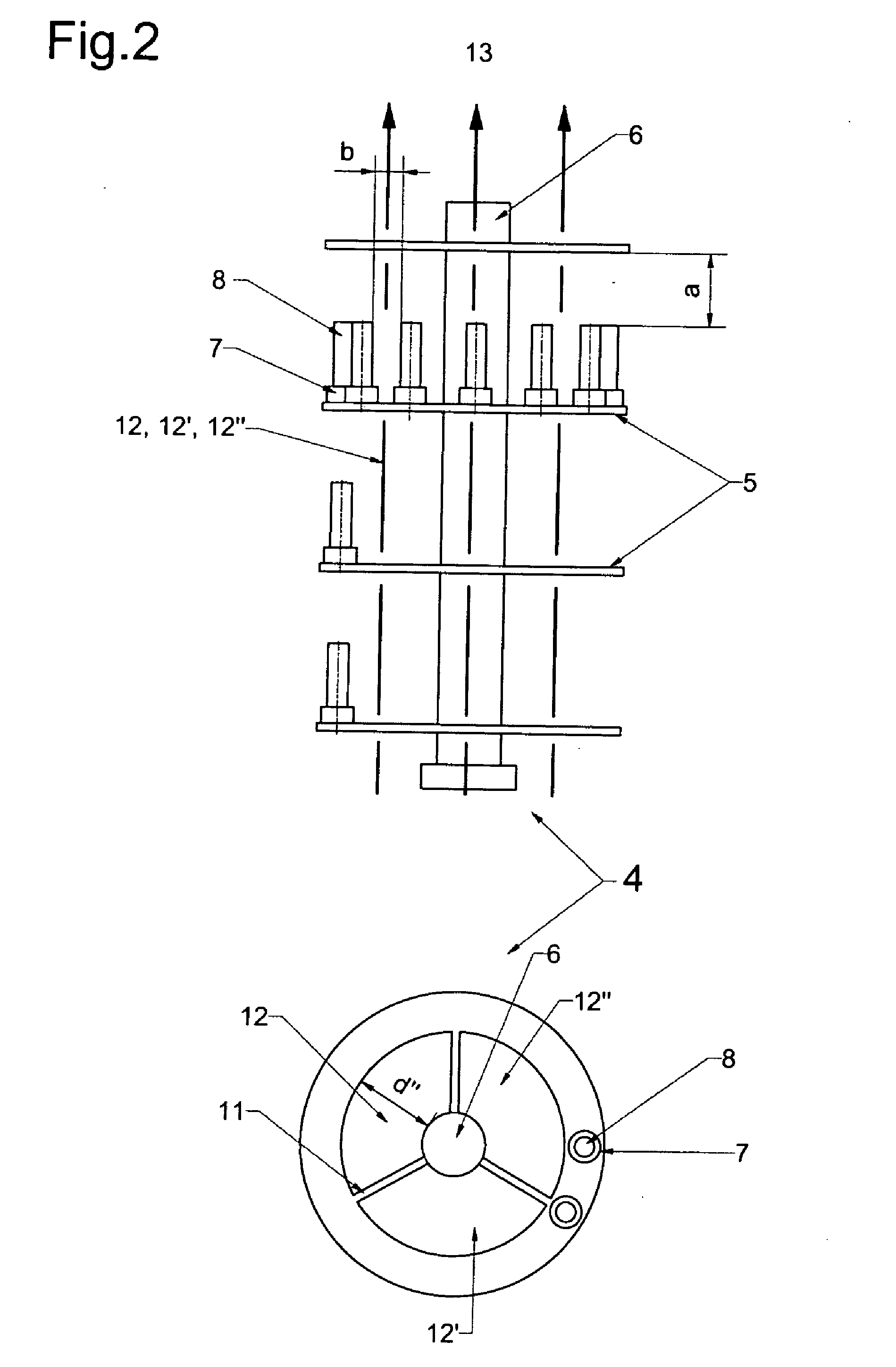
[0049]Here the workpieces were charged as in Example 1, additionally, two of 12 trees were replaced with an arrangement described as in FIG. 1. Alternatively, on one carousel loaded with 6 trees, additionally, 3 plasma boosters 1 as in FIG. 3 were utilized. In both cases a positive effect on the deposition rate was observed.


PUM

PropertyMeasurementUnit
pressureaaaaaaaaaa
pressureaaaaaaaaaa
pressureaaaaaaaaaa

Abstract

Vacuum treatment installation particularly for plasma coating workpieces has an arrangement for boosting and / or igniting a glow discharge plasma for the treatment of workpieces, and at least one hollow body of electrically conductive material, the hollow body including a hollow space and at least one entrance opening through which charge carriers flow in order to make possible ignition and operation of a plasma or to boost an existing plasma.

Description

CROSS-REFERENCE TO RELATED APPLICATIONS[0001]This is a divisional of U.S. patent application Ser. No. 12 / 874,624 filed Sep. 2, 2010, which is incorporated here by reference, which is a continuation of U.S. patent application Ser. No. 11 / 416,344 filed May 1, 2006, which is incorporated here by reference, which is now U.S. Pat. No. 7,798,097, and which claimed priority on Swiss patent application 00788 / 05, filed May 4, 2005, which priority claim is repeated here as well.BACKGROUNDField of the Invention[0002]The invention relates to a plasma booster for a plasma treatment installation, in particular for use in a vacuum coating installation and for a vacuum treatment method.[0003]Hot or cold cathodes are known, in which by applying a voltage between a cathode, for example a spiral-wound filament or a point with high negative potential, and an anode, electrons are extracted into the treatment space of a vacuum coating installation in order to increase the density of the charge carriers a...

Claims


Application Information

Patent Timeline
Patent Type & Authority Applications(United States)
IPC IPC(8): C23C16/50
CPCC23C14/22C23C16/0272C23C16/26C23C16/50H01J37/32009H01J37/32018H01J37/32
Inventor MASSLER, ORLAWEBERLE, HUBERTGSCHWEND, PATRICK
Owner OERLIKON SURFACE SOLUTIONS AG PFAFFIKON
Why Eureka
Try Eureka