Property determining apparatus for determining a property of an object

a technology of property determination and object, which is applied in the field of property determination apparatus, method and computer program for determining the property of an object, can solve the problems of inaccuracy in determining possible damage of the tissue, and achieve the effects of enhancing perfusion through the tissue, enhancing perfusion, and diffusing ultrasound pulses

Active Publication Date: 2013-02-14
KONINKLIJKE PHILIPS ELECTRONICS NV
View PDF5 Cites 12 Cited by
  • Summary
  • Abstract
  • Description
  • Claims
  • Application Information

AI Technical Summary

Benefits of technology

[0011]Since the scatter determination unit determines at least one scatter value being indicative of a scatter of the ultrasound pulse by the fluid and since the property determination unit is adapted to determine a property of the object depending on the at least one scatter value, a property, which is related to the perfusion by the fluid, can more directly be determined based on the at least one scatter value. Thus, it is not necessary to use a very indirect measure like a detection of bubble formation, which reflects high temperature in tissue, but which is not directly linked to, for example, the extent of tissue damage, for determining a property of the object. This increases the accuracy of determining a property of the object.
[0030]The object influencing apparatus preferentially comprises a control unit for controlling the object influencing unit, wherein the control unit is adapted to control the object influencing unit depending on the property of the object, which is determined by the property determination unit of the property determining apparatus. As already mentioned above, the property of the object is, for example, the ablation depth. If the object influencing apparatus is an ablation apparatus, which is controlled depending on the ablation depth, the ablation apparatus can be controlled such that a desired ablation depth can be reached. Moreover, it can be determined whether a vessel, in particular, an artery or a vein, is located in front of an ablation electrode as the property of the object. The ablation apparatus can, for example, be controlled such that the ablation is not started or the ablation is stopped, if a vessel has been detected in front of the ablation electrode. In general, by controlling the ablation of the object depending on the determined property of the object, the ablation of the object can be improved.

Problems solved by technology

This monitoring leads to inaccuracies in determining possible damages of the tissue, because bubble formation reflects only high temperature in the tissue, but is not directly linked to the extent of tissue damage.

Method used


Image

  • Property determining apparatus for determining a property of an object
  • Property determining apparatus for determining a property of an object
  • Property determining apparatus for determining a property of an object

Examples


Embodiment Construction

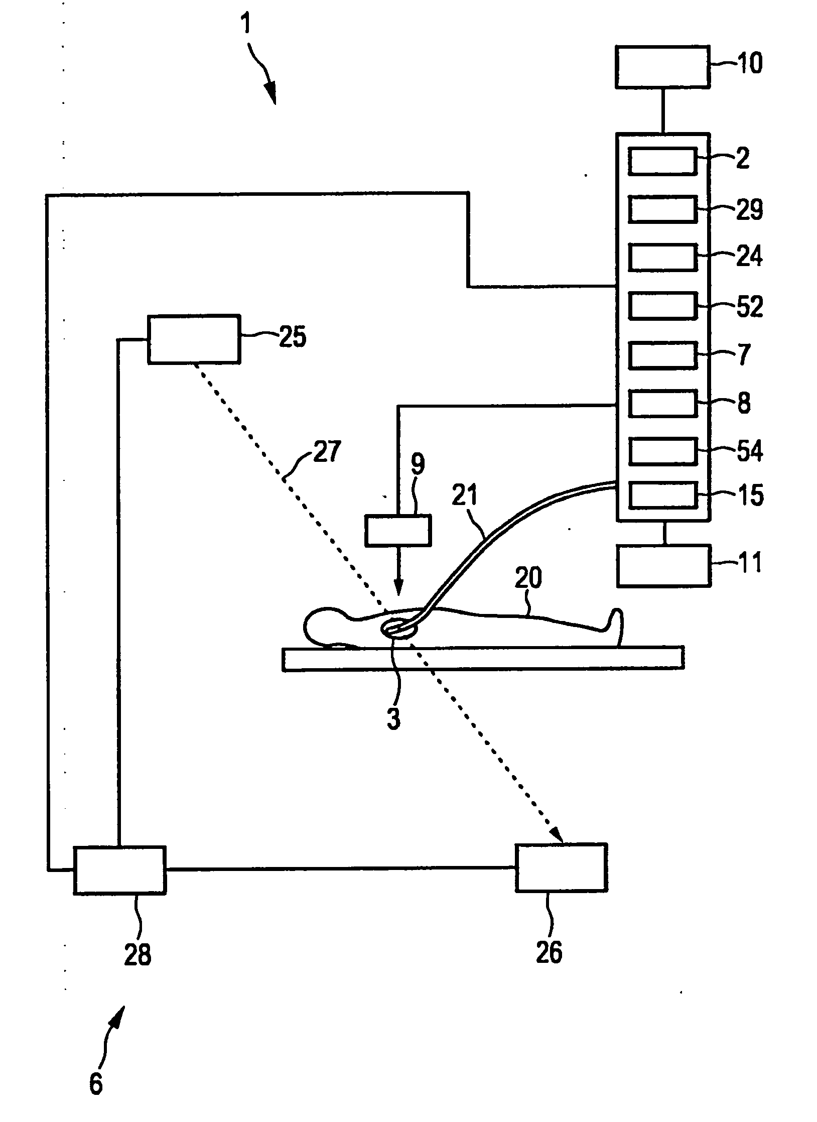
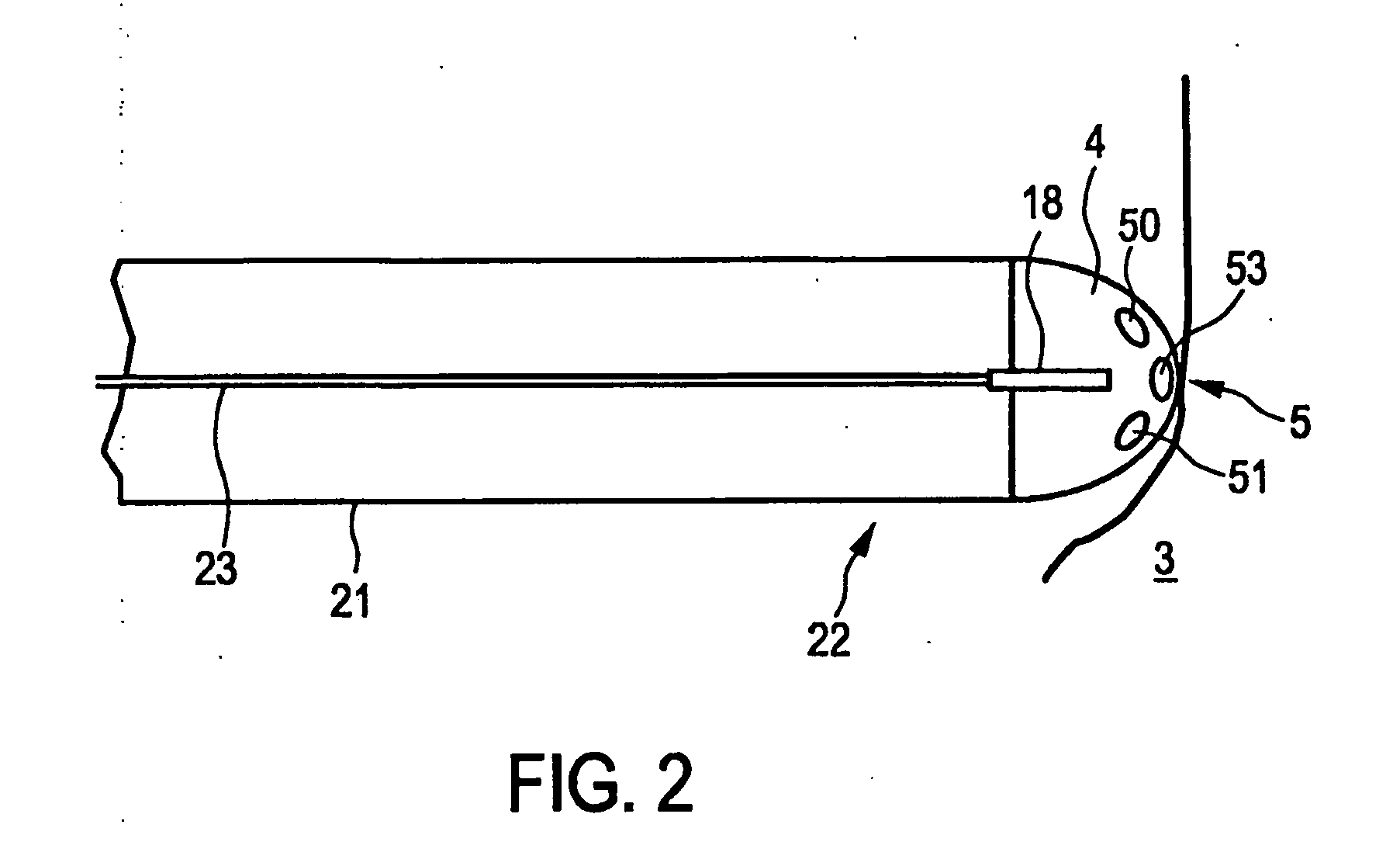
[0057]FIG. 1 shows schematically and exemplarily an ablation apparatus 1 for ablating an object. The ablation apparatus 1 comprises an image providing unit 2 for providing an image of the object 3 being, in this embodiment, a heart of a person 20. The ablation apparatus 1 further comprises a catheter 21 for applying energy to an inner wall of the heart 3. The tip 22 of the catheter 21 is schematically and exemplarily shown in FIG. 2.

[0058]The catheter tip 22 comprises an ablation electrode 4 for applying energy to the wall of the heart 3 at a location 5 for ablating the wall. The ablation electrode 4 is connected with an energy source 24 via an electrical connection 23 for providing electrical energy at the location 5. Preferentially, the energy source 24, the electrical connection 23 and the ablation electrode 4 are adapted to apply radio frequency (RF) energy to the heart 3 at the location 5. The electrical connection 23 is preferentially a wire. The ablation electrode 4, the elec...


PUM


Abstract

A monitoring apparatus for monitoring an ablation procedure applied to an object comprises an ultrasound signal providing unit for providing an ultrasound signal. The ultrasound signal is produced by sending ultrasound pulses out to the object, by subsequently receiving dynamic echo series after the ultrasound pulses have been reflected by the object, and finally by generating the ultrasound signal depending on the received dynamic echo series, whereby ultrasound scattering properties of the object are determined that represent blood perfusion. The monitoring apparatus further comprises an ablation depth determination unit for determining an ablation depth from the provided ultrasound signal.

Description

FIELD OF THE INVENTION[0001]The invention relates to a property determining apparatus, method and computer program for determining a property of an object. The invention relates further to an object influencing apparatus comprising the property determining apparatus, a corresponding object influencing method and a corresponding object influencing computer program.BACKGROUND OF THE INVENTION[0002]WO 2006 / 064495 A1 discloses a method for monitoring heat damage to tissue during a heat ablation procedure. While a certain part of the tissue is ablated, ultrasound images of neighboring parts of the tissue are acquired, and from these ultrasound images a parameter is extracted, which is indicative of a biological response of the neighboring parts of the tissue to heat. In an embodiment, the parameter is the accumulation of bubbles and a damage of the neighboring parts of the tissue is determined based on this parameter. The aim of this monitoring method is the detection of unwanted damages...

Claims


Application Information

Patent Timeline
Patent Type & Authority Applications(United States)
IPC IPC(8): A61B8/06A61B8/12
CPCA61B6/503A61B8/445A61B8/0833A61B8/0891A61B8/12A61B8/4472A61B17/3403A61B18/0206A61B18/1492A61B19/5225A61B2017/00053A61B2017/00106A61B2017/3413A61B2018/00577A61B2018/0212A61B2018/1861A61B2019/2211A61B2019/2242A61B2019/5236A61B2019/5238A61B2019/524A61B2019/5251A61B2019/5265A61B2019/528A61B2217/007A61B6/504A61B8/486A61B34/71A61B2034/301A61B2090/376A61B2090/3784A61B90/37A61B2090/374A61B2090/3762A61B2034/2051A61B2034/2065
Inventor HARKS, GODEFRIDUS ANTONIUSZUO, FEIDELADI, SZABOLCSFOKKENROOD, STEVEN ANTONIE WILLEMMIHAJLOVIC, NENAD
Owner KONINKLIJKE PHILIPS ELECTRONICS NV
Why Eureka
Try Eureka