Intelligent microgrid controller

a micro-grid and intelligent technology, applied in non-electric variable control, process and machine control, instruments, etc., can solve the problems of reducing the efficiency of the generator, the rated output of such a generator may exceed the present need for electrical power, and the difficulty of efficient control of the micro-grid asset, so as to increase the overall energy output efficiency, and increase the overall efficiency of the one or more power generation units

Active Publication Date: 2013-02-14
ROCKY RES
View PDF7 Cites 131 Cited by
  • Summary
  • Abstract
  • Description
  • Claims
  • Application Information

AI Technical Summary

Benefits of technology

[0005]In one embodiment, a system for increasing efficiency of power generation, distribution and delivery, includes: a microgrid controller having a plurality of inputs and outputs; one or more power generation units electrically connected to a first input on the microgrid controller; an electrical storage unit electrically connected to a second input on the microgrid controller; and an electrical load electrically connected to an output of the microgrid controller, and wherein the microgrid controller comprises a control module connected to the one or more power generation units and configured to increase the overall efficiency of the one or more power generation unit.
[0006]In another embodiment, a microgrid controller, includes: a plurality of inputs configured to electrically connect to a plurality of power generation units; a plurality of outputs configured to electrically connect to a plurality of electr

Problems solved by technology

Because microgrids may use many different types of electrical generation sources, including renewable and non-renewable energy, and may include many different types of loads to service, efficient control of microgrid assets is challenging.
However, the rated output of such a generator may exceed the present need for electrical power on the microgrid at any one time.
Altering the output of the electromechanical generator such that it

Method used


Image

  • Intelligent microgrid controller
  • Intelligent microgrid controller
  • Intelligent microgrid controller

Examples


Embodiment Construction

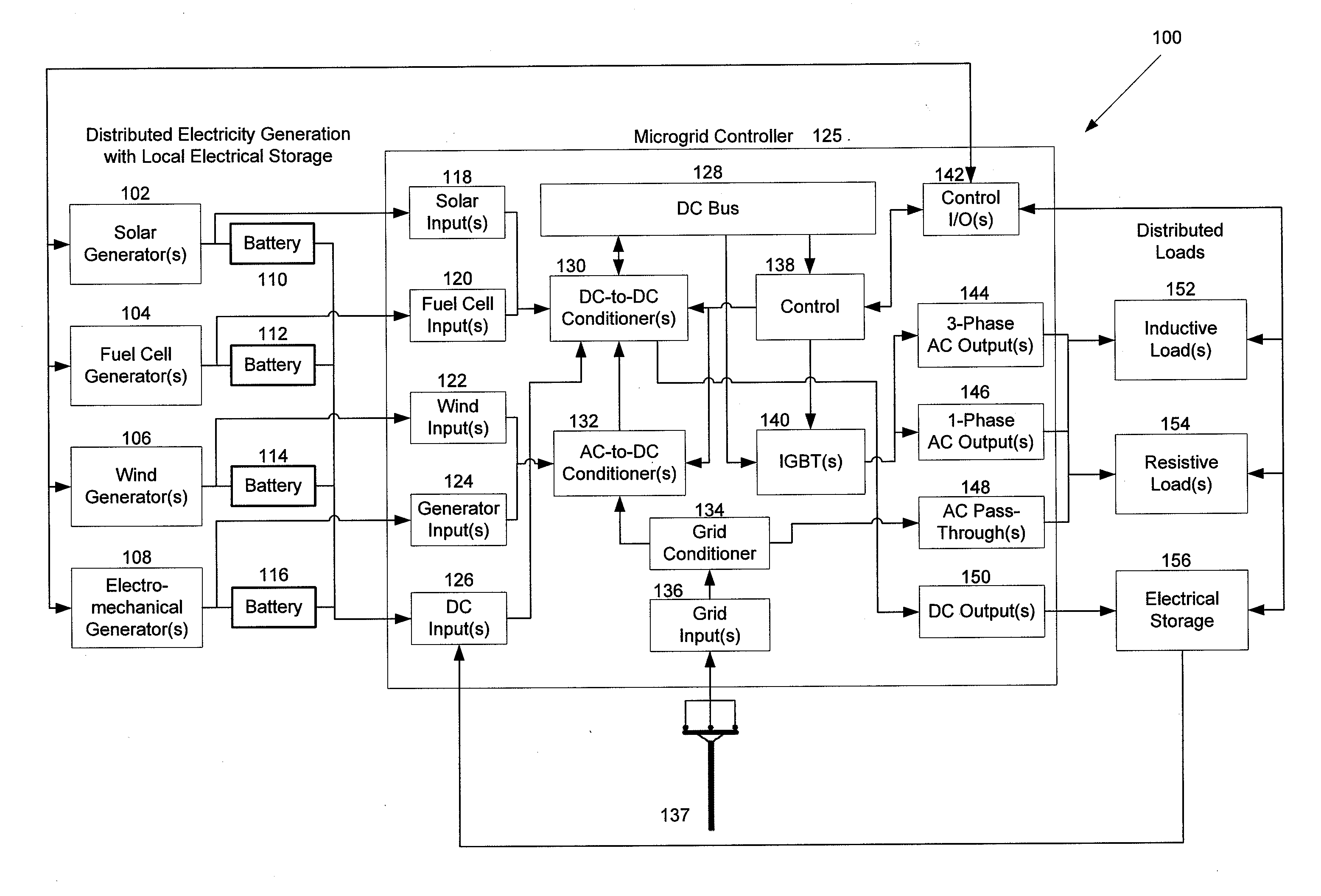
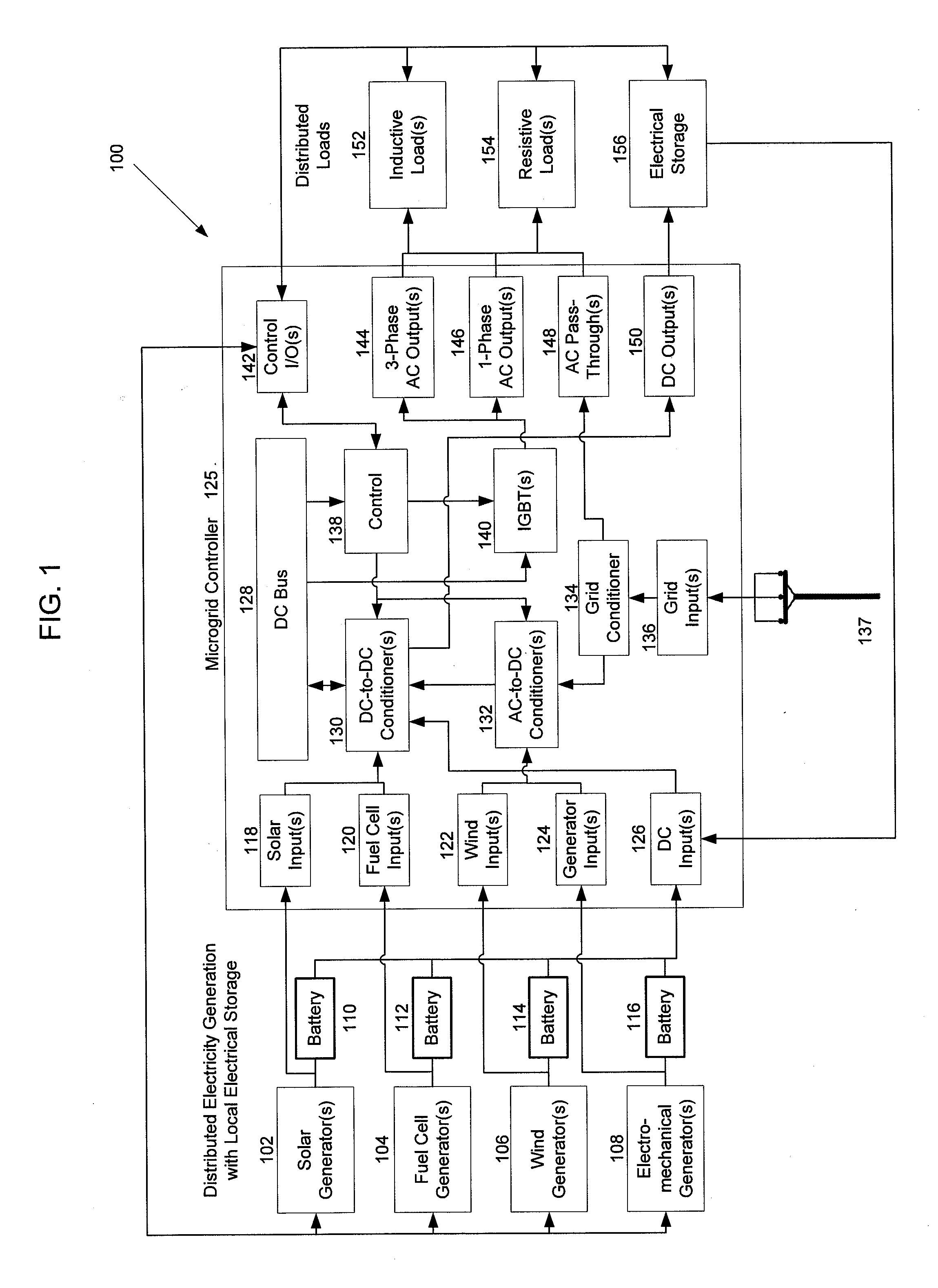
[0015]Embodiments relate to microgrid controllers that are used to intelligently control power generation and usage on a microgrid. Embodiments of microgrid systems may include multiple types of electrical generation sources electrically connected to a microgrid controller. As described in more detail with reference to FIG. 1, below, electrical generation sources may include solar generators, wind generators, fuel cell generators, electromechanical generators, and other types of power generation machinery.

[0016]One embodiment relates to a microgrid controller that increases the efficiency of electromechanical generators providing microgrid power. Electromechanical generators that use fuel-burning engines tend to be most efficient at a particular engine speed based on the generator's design and particular electrical output level. For example, some generators may output 10 kilowatts per hour at 4000 revolutions per minute (RPM) and use 1 gallon of fuel per hour, which corresponds to a...


PUM


Abstract

A microgrid controller may control the generation, distribution, storage and use of electrical power on a microgrid. Embodiments of a microgrid controller may include inputs for different types of power (e.g. AC and DC) or power sources (e.g. wind and solar), an input for utility grid power, electrical equipment for conditioning the electrical power received from the multiple sources (e.g. rectifiers and inverters), outputs to multiple types of loads (e.g. three-phase AC and single-phase AC) and control circuitry designed to control the generation, storage, distribution and usage of electrical power on the microgrid. Embodiments of microgrid systems may include multiple types of electrical generation sources (e.g. wind, solar, electromechanical and fuel cell), multiple types of electrical loads (e.g. inductive and resistive), electrical storage units (e.g. batteries) and a microgrid controller.

Description

FIELD OF THE INVENTION[0001]Embodiments relate to a system and method for controlling power utilization on a microgrid. More particularly, embodiments relate to a system and method for increasing the efficiency of power production within a microgrid.BACKGROUND OF THE INVENTION[0002]A microgrid is a localized grouping of electrical generation, electrical energy storage, and electrical loads. Microgrids are often connected to a traditional utility grid and may operate as connected to the utility grid or completely independent from the utility grid. Microgrid electrical generation sources can include, for example, wind turbines, photovoltaic or “solar” panels, electromechanical generators, turbine generators, fuel cells, and other types of electrical generation machinery. By having local and diverse electrical generation sources and the ability to operate independent of a utility grid, microgrids may provide highly reliable and cost effective electric power to many types of installatio...

Claims


Application Information

Patent Timeline
IPC IPC(8): G06F1/28
CPCH02J3/38H02J3/383H02J3/386Y02E10/763H02J7/34Y02E10/563H02J3/387H02J2310/10H02J2300/10H02J2300/30H02J2300/28H02J2300/24H02J3/381Y02E10/56Y02E10/76H02J3/46
Inventor ROCKENFELLER, UWEKHALILI, KAVEH
Owner ROCKY RES
Why Eureka
Try Eureka