Power and control pod for a subsea artificial lift system

a technology of power and control pods and artificial lifts, applied in the direction of sealing/packing, instruments, borehole/well accessories, etc., to achieve the effect of reducing the voltage of the dc power signal

Active Publication Date: 2013-02-21
SCHLUMBERGER TECH BV
View PDF20 Cites 47 Cited by
  • Summary
  • Abstract
  • Description
  • Claims
  • Application Information

AI Technical Summary

Benefits of technology

[0006]Embodiments of the present invention generally relate to a power and control pod for subsea artificial lift system. In one embodiment, a method of operating a downhole tool in a subsea wellbore includes: supplying a direct current (DC) power signal from a dry location to a subsea control pod; converting the DC power signal to an alternating current (AC) power signal by the control pod; and supplying the AC power signal from the control pod, into the subsea wellbore, and to the downhole tool.
[0007]In another embodiment, a subsea c

Problems solved by technology

There has been limited deployment of cable inserted in coil tubing where the coiled tubing is utilized to support the weight of the equipment and cable, althoug

Method used


Image

  • Power and control pod for a subsea artificial lift system
  • Power and control pod for a subsea artificial lift system
  • Power and control pod for a subsea artificial lift system

Examples


Embodiment Construction

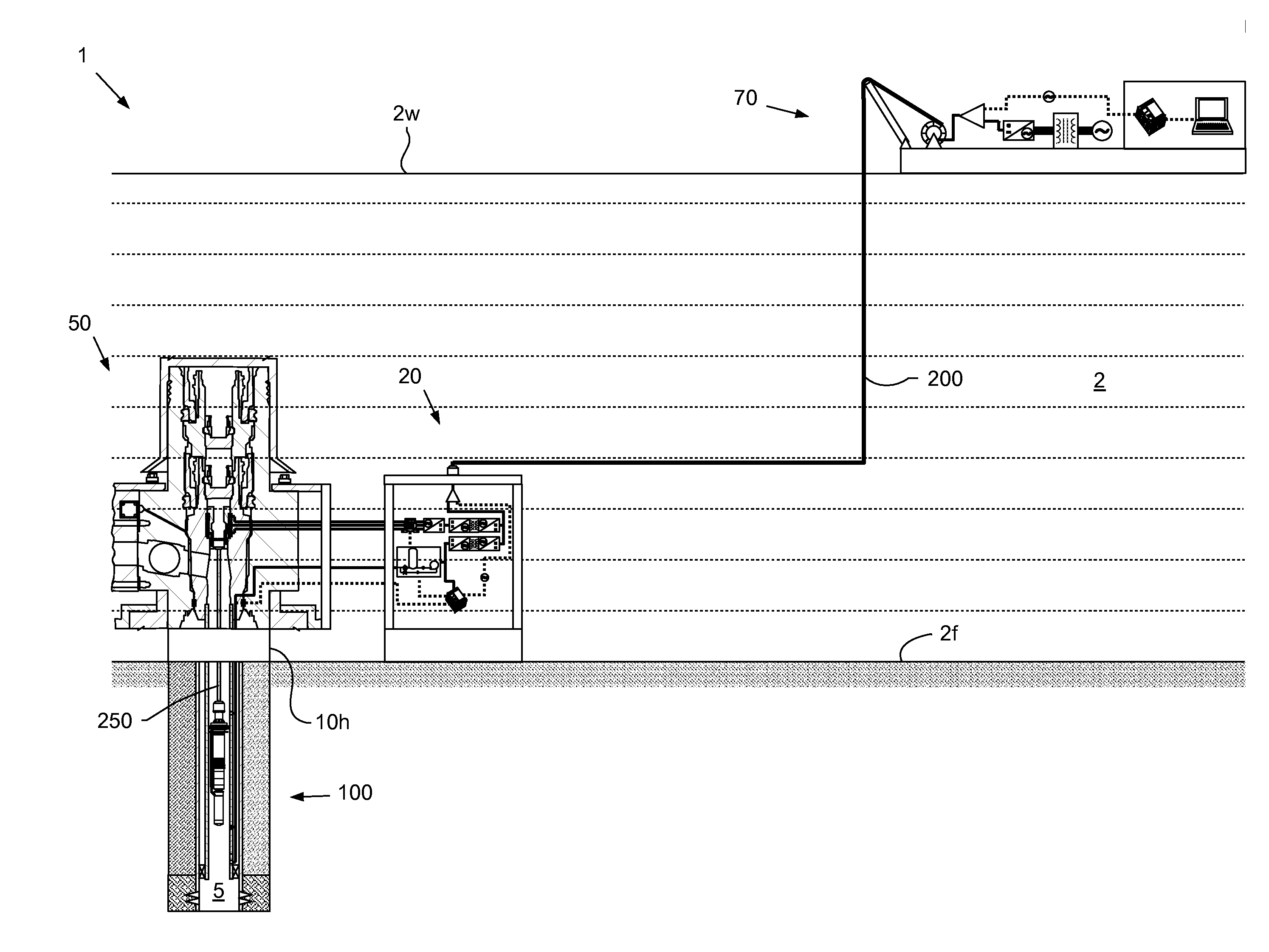
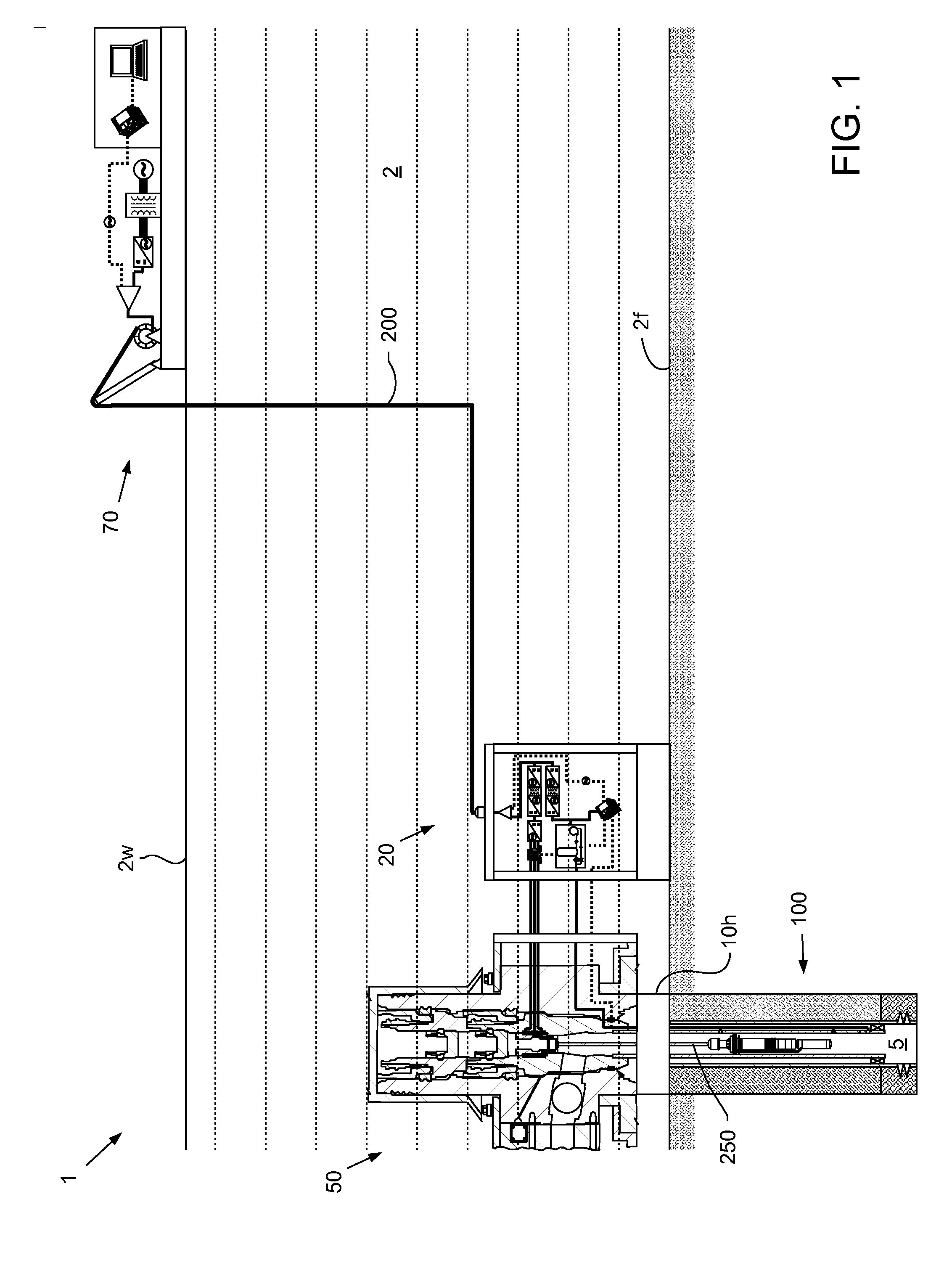
[0015]FIG. 1 illustrates a subsea artificial lift system (ALS) 1, according to one embodiment of the present invention. The ALS 1 may include an electric submersible pump (ESP) 100, a deployment cable 250, a subsea production (aka Christmas) tree 50, a subsea control pod 20, an umbilical 200, and a launch and recovery system (LARS) 70. A length of the umbilical 200 may include a vertical depth portion and a horizontal step-out portion. The umbilical length may be greater than, equal to, or substantially greater than five hundred feet, such as one-quarter, one-half, three-quarters, one, two, or five miles.

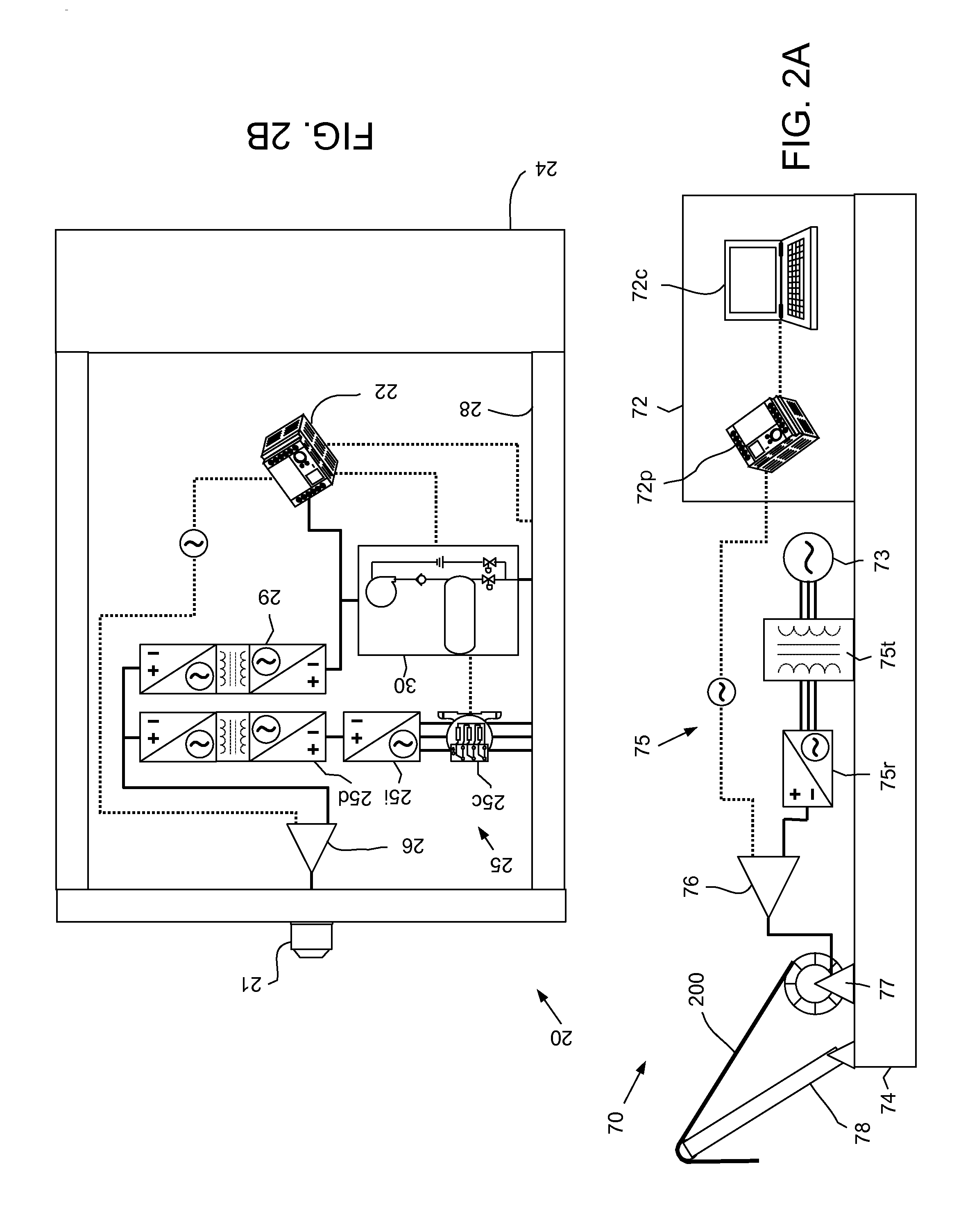
[0016]FIG. 2A illustrates the LARS 70. The pod 20 may be launched into the sea 2 from a support vessel (not shown) by the LARS 70. Once deployed, the LARS 70 may be transported and loaded onto a control platform (not shown). The control platform may have personnel stationed onboard or be automated. If automated, the control platform may be in communication with an onshore command ce...


PUM


Abstract

Embodiments of the present invention generally relate to a power and control pod for subsea artificial lift system. In one embodiment, a method of operating a downhole tool in a subsea wellbore includes: supplying a direct current (DC) power signal from a dry location to a subsea control pod; converting the DC power signal to an alternating current (AC) power signal by the control pod; and supplying the AC power signal from the control pod, into the subsea wellbore, and to the downhole tool.

Description

CROSS-REFERENCE TO RELATED APPLICATIONS[0001]This application claims benefit of U.S. provisional patent application Ser. No. 61 / 524,087, filed Aug. 16, 2011, which is herein incorporated by reference.BACKGROUND OF THE INVENTION[0002]1. Field of the Invention[0003]Embodiments of the present invention generally relate to a power and control pod for subsea artificial lift system.[0004]2. Description of the Related Art[0005]The oil industry has utilized electric submersible pumps (ESPs) to produce high flow-rate wells for decades, the materials and design of these pumps has increased the ability of the system to survive for longer periods of time without intervention. These systems are typically deployed on the tubing string with the power cable fastened to the tubing by mechanical devices such as metal bands or metal cable protectors. Well intervention to replace the equipment requires the operator to pull the tubing string and power cable requiring a well servicing rig and special spo...

Claims


Application Information

Patent Timeline
IPC IPC(8): E21B41/00E21B41/04G05F3/00E21B43/16
CPCE21B43/128E21B33/0355
Inventor DRABLIER, DIDIERGRIFFITHS, NEILBESPALOV, EUGENE
Owner SCHLUMBERGER TECH BV
Why Eureka
Try Eureka