Adjustable data drivers and methods for driving data signals

a technology of data signals and drivers, applied in the field of data drivers, can solve problems such as compromising performance, affecting signal transitions on one signal line, and reducing the size of the semiconductor integrated circui

Active Publication Date: 2013-02-21
MICRON TECH INC
View PDF2 Cites 18 Cited by
  • Summary
  • Abstract
  • Description
  • Claims
  • Application Information

AI Technical Summary

Problems solved by technology

Semiconductor integrated circuits are continually becoming smaller due to demands for device compactness and increased circuit complexity.
Due to the proximity of the signal lines, issues of crosstalk and pattern dependent impedance mismatch may cause signal transitions on one signal line to be affected by signal transitions on one or more adjacent signal lines.
As a result, the signals may take longer to reach a desired logic level thus compromising performance.
Transitioning signals on adjacent signal lines may also result in pattern dependent impedance mismatch, as previously mentioned.
Pattern dependent impedance mismatch may cause adjacent signal lines having transitioning signals to effectively change impedance from a nominal (e.g., expected) impedance.
This may result in signal reflections on the signal line and signal interference, again compromising performance.

Method used


Image

  • Adjustable data drivers and methods for driving data signals
  • Adjustable data drivers and methods for driving data signals
  • Adjustable data drivers and methods for driving data signals

Examples


Embodiment Construction

[0011]Certain details are set forth below to provide a sufficient understanding of embodiments of the invention. However, it will be clear to one skilled in the art that embodiments of the invention may be practiced without these particular details. Moreover, the particular embodiments of the present invention described herein are provided by way of example and should not be used to limit the scope of the invention to these particular embodiments. In other instances, well-known circuits, control signals, timing protocols, and software operations have not been shown in detail in order to avoid unnecessarily obscuring the invention.

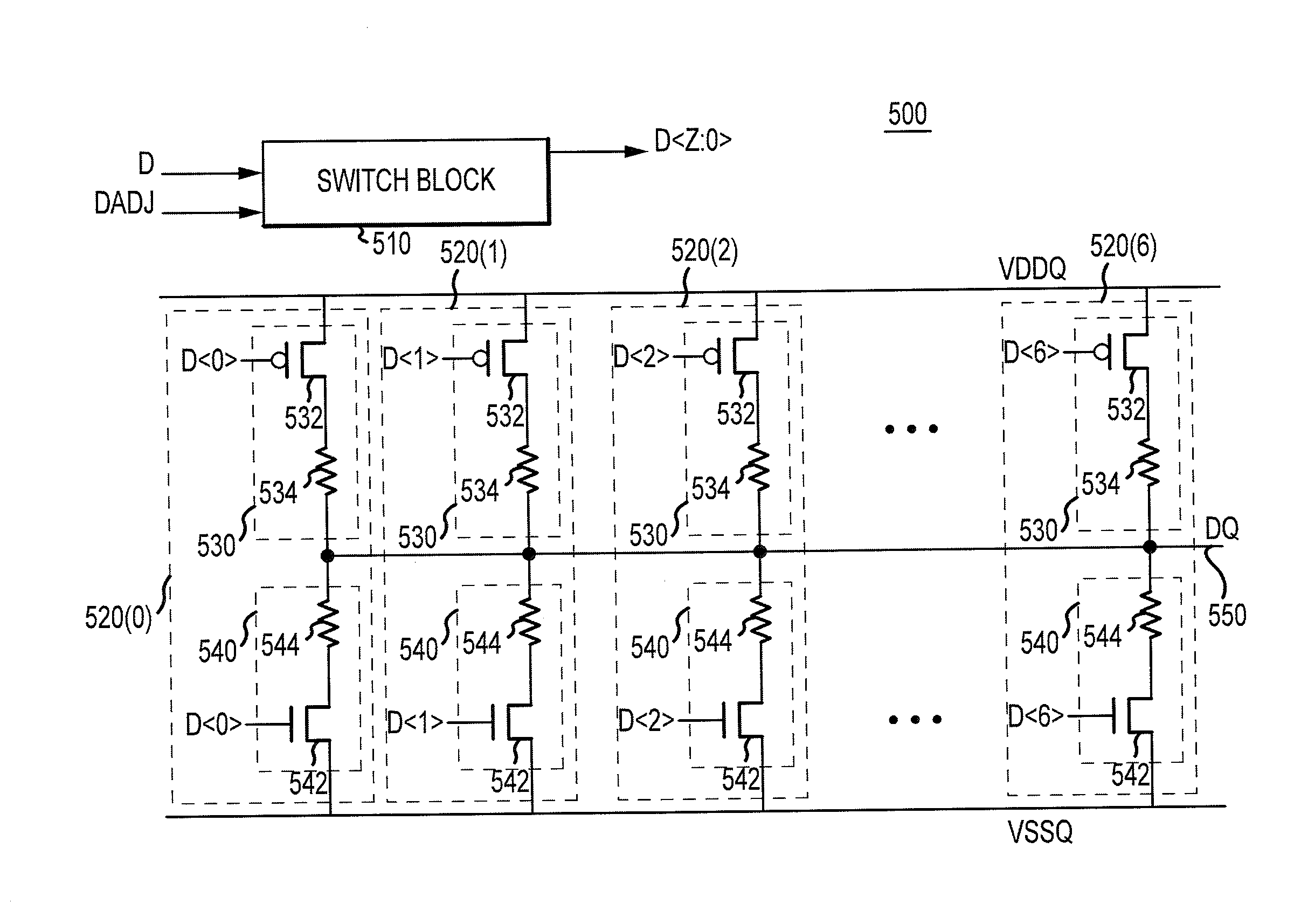
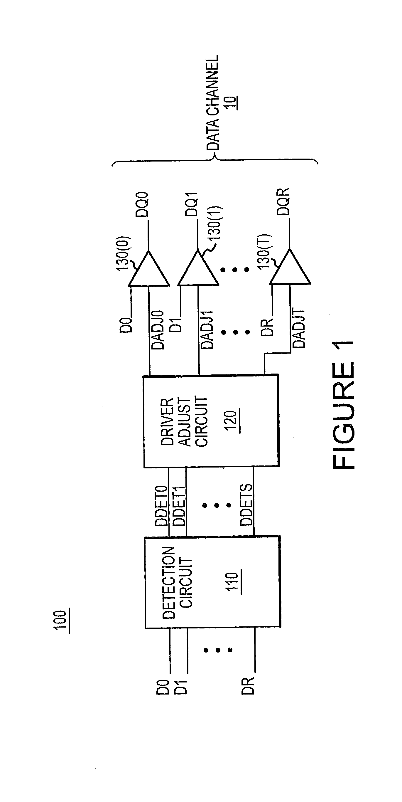
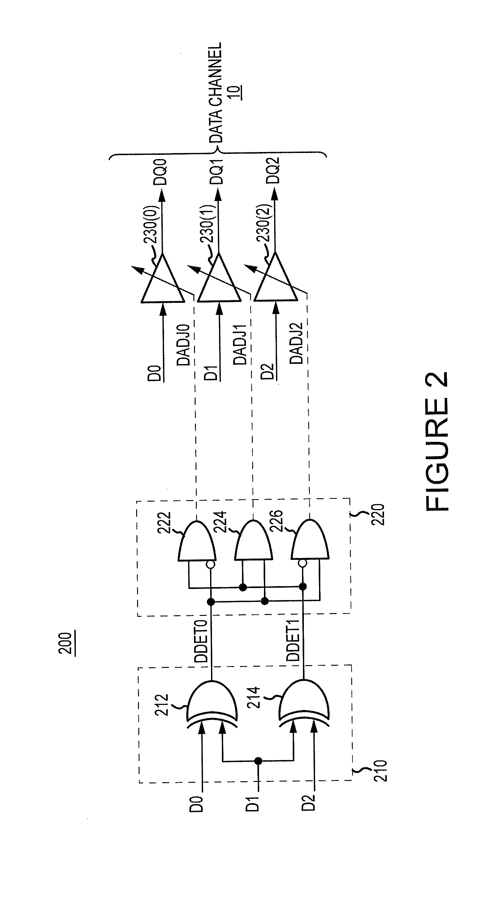
[0012]FIG. 1 illustrates an apparatus in the form of an output signal driver circuit 100 according to an embodiment of the invention. The output signal driver circuit 100 includes a detection circuit 110 configured to receive a group of data signals D0-DR and provide data detection signals DDET0-DDETS to a driver adjust circuit 120. The DDET0-DDETS signals ...


PUM


Abstract

Apparatuses and methods for driving input data signals onto signal lines as output data signals are disclosed. An example apparatus includes a detection circuit, a driver adjust circuit, and a data driver. The detection circuit is configured to detect a characteristic(s) of a group of input data signals to be driven onto adjacent signal lines. A characteristic could be, for example, a particular combination of logic levels and / or transitions for, the group of input data signals. The driver adjust circuit is configured to provide a driver adjustment signal based at least in part on a detection signal, that is provided by the detection circuit. A data driver is configured to drive a respective one of the group of input data signals as a respective one of the output data signals, wherein the data driver is adjusted based at least in part on the driver adjustment signal.

Description

TECHNICAL FIELD[0001]Embodiments of the present invention relate generally to data drivers, and more specifically, in one or more illustrated embodiments, to data drivers that are adjustable based at least in part on a characteristic(s) of data signals to be driven onto signal lines by the data drivers.BACKGROUND OF THE INVENTION[0002]Semiconductor integrated circuits are continually becoming smaller due to demands for device compactness and increased circuit complexity. Electrical circuitry have shrunken and are typically positioned in very close proximity to increase circuit density. As a result, closely positioned circuitry may influence the operation of one another. For example, output signal drivers often drive signals onto parallel signal lines that are in close proximity to one another, such as onto a data channel. Typical data channels have a plurality of closely spaced signal lines on which data signals are transmitted.[0003]Due to the proximity of the signal lines, issues ...

Claims


Application Information

Patent Timeline
Patent Type & Authority Applications(United States)
IPC IPC(8): H03K19/003
CPCH03K19/0005H03K19/08H03K19/017581G11C7/1057G11C29/022G11C29/028
Inventor HOLLIS, TIMOTHY M.SCHOBER, BRUCE W.
Owner MICRON TECH INC
Why Eureka
Try Eureka