Programmable illuminator for a photolithography system

a photolithography system and illuminator technology, applied in the field of photolithography systems, can solve the problems of adversely affecting the performance of the photolithography system, no effective way to control the shutter-blade switching time, and limited mechanical considerations

Inactive Publication Date: 2013-02-21
ULTRATECH INT INC
View PDF8 Cites 11 Cited by
  • Summary
  • Abstract
  • Description
  • Claims
  • Application Information

AI Technical Summary

Benefits of technology

[0007]An aspect of the disclosure is a programmable illuminator for a photolithography system for illuminating over an optical path a reticle having a reticle field. The programmable illuminator includes, in order along an optical axis, a light source that generates actinic light, and a first optical system configured to receive the actinic light from the illuminator. The first optical system has at least one uniformizing element configured to form uniformized actinic light from the received actinic light. A programmable micro-mirror device is arranged downstream of the first optical system and includes an array of micro-mirrors....

Problems solved by technology

There is no effective way to control that shutter-blade switching time apart from dramatically increasing the speed and acceleration of the shutter blades.
However, this approach is limited by mechanical considerations.
The increased acceleration and deceleration required cause vibrations in the optical system that adversely affect the performance of the photolithography system.
Thus, using a conventional mechanical shutter to make small chan...

Method used


Image

  • Programmable illuminator for a photolithography system
  • Programmable illuminator for a photolithography system
  • Programmable illuminator for a photolithography system

Examples


Embodiment Construction

[0020]Reference is now made in detail to the present preferred embodiments of the disclosure, examples of which are illustrated in the accompanying drawings. Whenever possible, the same reference numbers and symbols are used throughout the drawings to refer to the same or like parts.

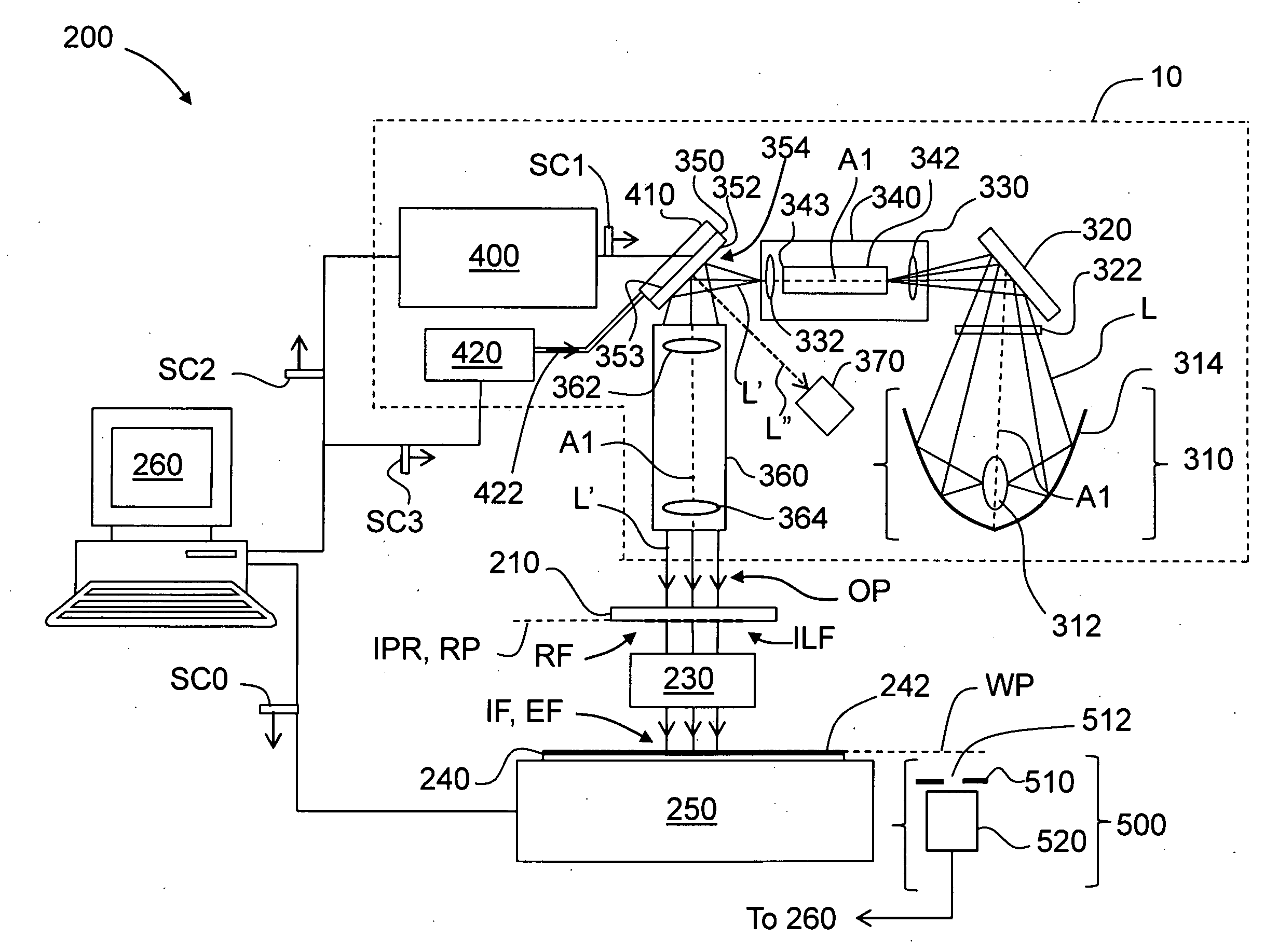
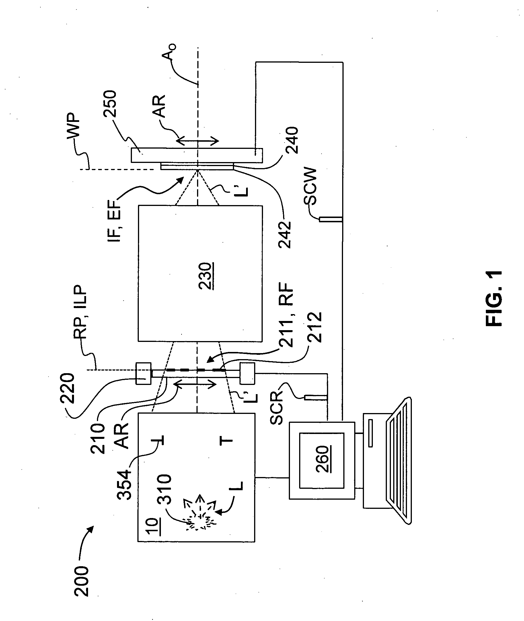
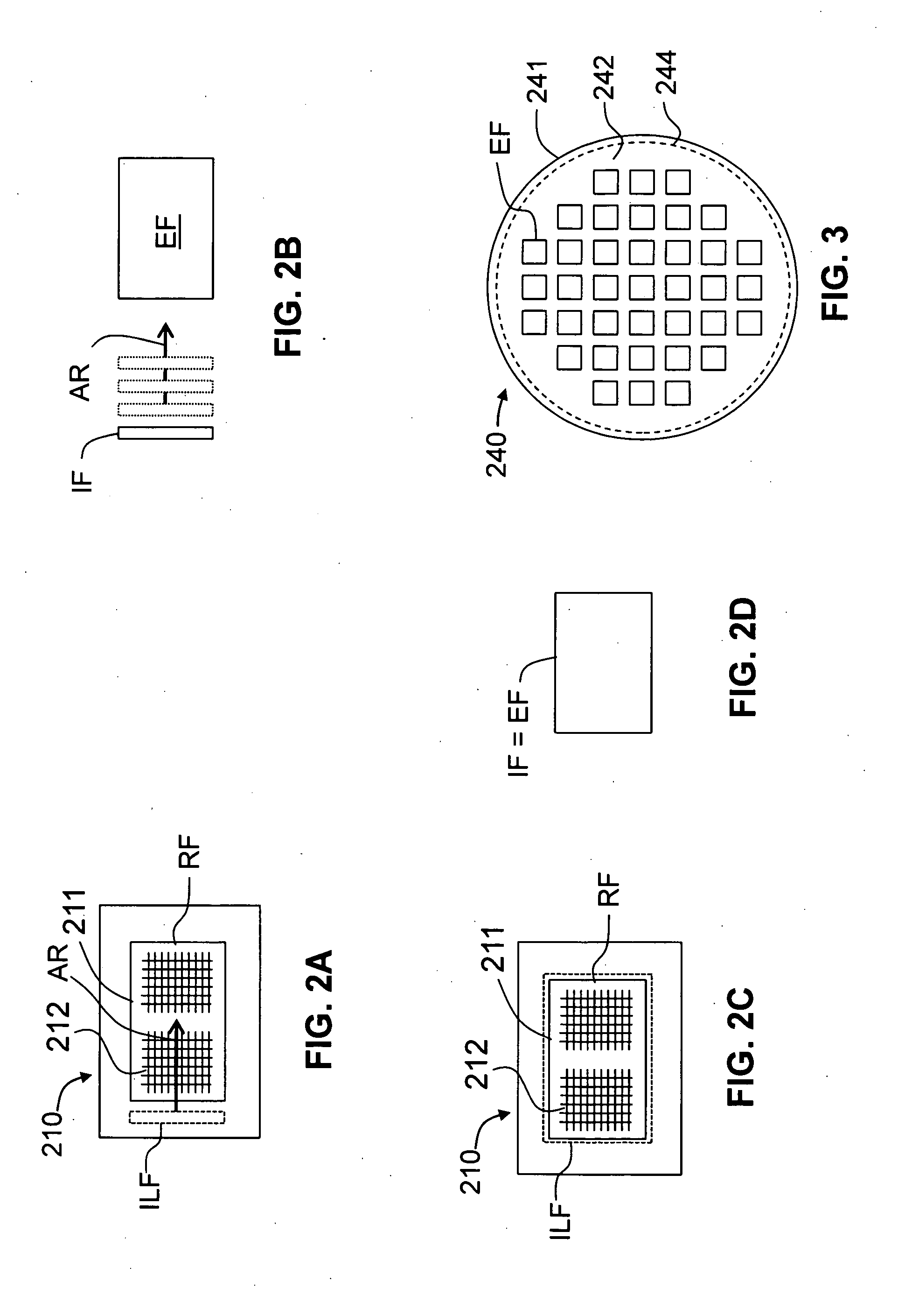
[0021]The disclosure is directed to inter alia a programmable illuminator for a photolithography system that uses a reticle or mask. An example photolithography system is first described, followed by a detailed description of an example programmable illuminator that is suitable for use in the example photolithography system.

Photolithography System

[0022]An example embodiment of the disclosure is a photolithography system that uses the programmable illuminator of the present disclosure. Example photolithography systems in which the programmable illuminator disclosed herein can be adapted for use are described in U.S. Pat. Nos. 7,177,099; 7,148,953; 7,116,496; 6,863,403; 6,813,098; 6,381,077; and 5,410,434,...


PUM


Abstract

A programmable illuminator for a photolithography system includes a light source, a first optical system having a light uniformizing element, a programmable micro-mirror device, and a second optical system that forms an illumination field that illuminates a reticle. The programmable micro-mirror device can be configured to perform shutter and edge-exposure-blocking functions that have previously required relatively large mechanical devices. Methods of improving illumination field uniformity using the programmable illuminator are also disclosed.

Description

FIELD[0001]The present disclosure relates generally to photolithography systems, and in particular to a programmable illuminator for a photolithography system.BACKGROUND ART[0002]A photolithography system has as its basic components an illuminator with a light source, a patterned reticle, a projection lens and a photosensitive (e.g., photoresist-coated) wafer. The illuminator illuminates the reticle with light from the light source. Light transmitted by or reflected from the reticle is then imaged by the projection lens onto the photosensitive wafer. The photosensitive wafer is then processed to form a pattern on the wafer. The photolithographic exposure process and post-exposure process is repeated with a number of different reticles to form on the wafer a semiconductor structure that defines an integrated circuit.[0003]The photolithography system needs to provide a precise amount of exposure energy (i.e., an “exposure dose”) to the photosensitive wafer over a well-defined region (...

Claims


Application Information

Patent Timeline
IPC IPC(8): G03B27/54
CPCG02B26/0833G03F7/70558G03F7/70066
Inventor ZLATANOV, BORISLAVHAWRYLUK, ANDREW M.
Owner ULTRATECH INT INC
Why Eureka
Try Eureka