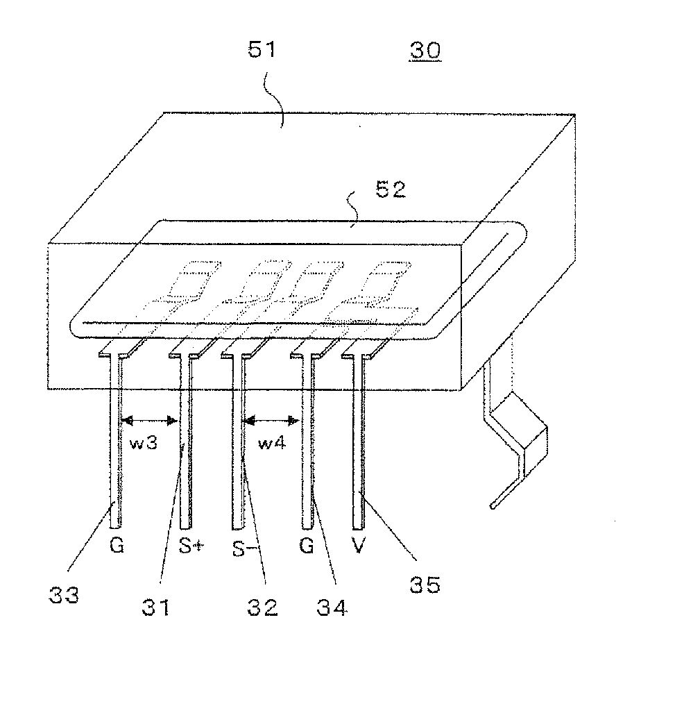
High-speed interface connector
a high-speed interface and connector technology, applied in the direction of coupling contact members, coupling device connections, two-part coupling devices, etc., can solve the problems of reducing convenience and being susceptible to external noise, and achieve the effect of reducing the degradation of the quality of differential signals
- Summary
- Abstract
- Description
- Claims
- Application Information
AI Technical Summary
Benefits of technology
Problems solved by technology
Method used
Image
Examples
reference example 1
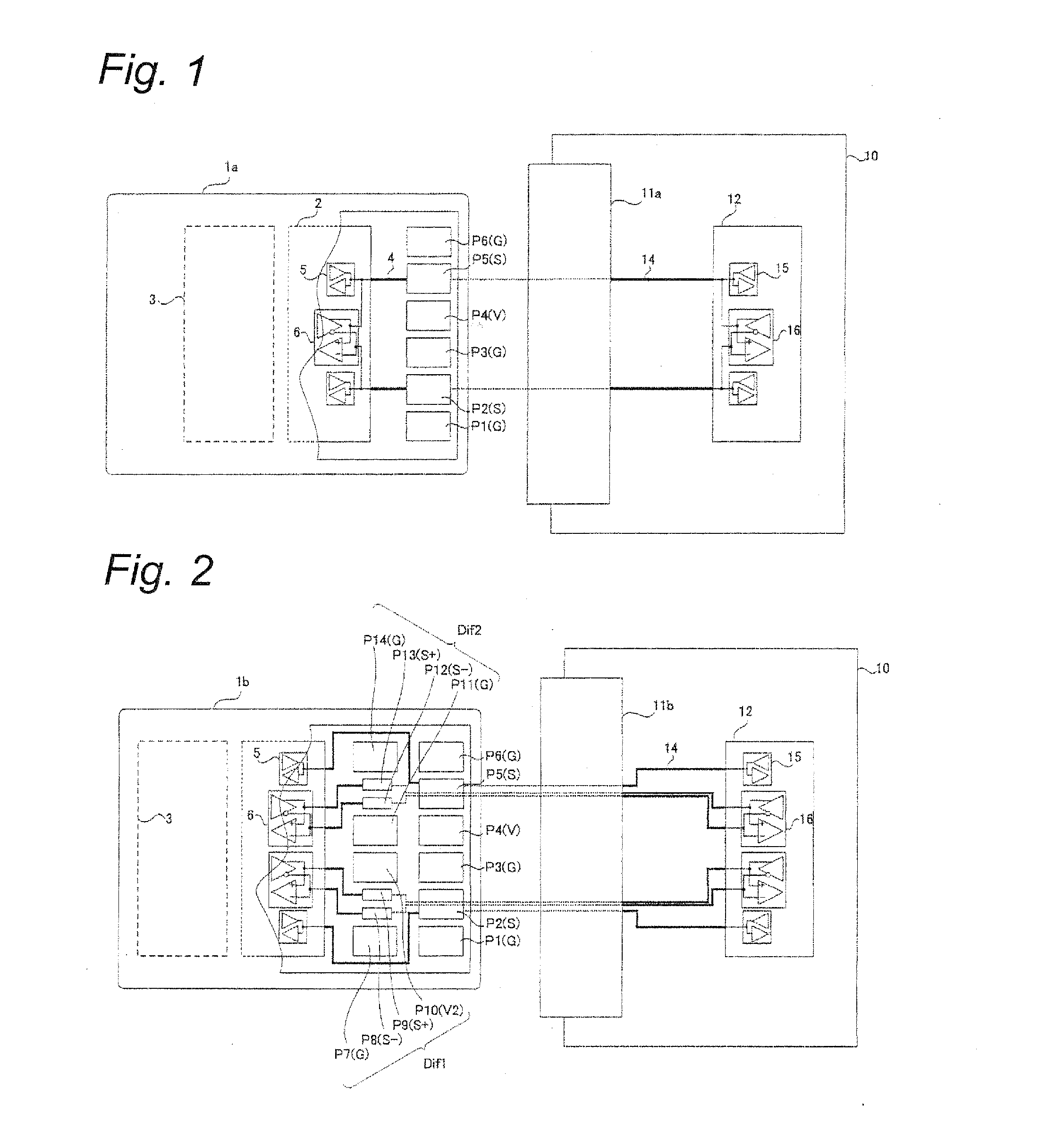
[0043]One of these is to share existing signal pins P(S) of a memory card as illustrated inFIG. 1, between both transmission systems of single-ended transmission and differential transmission (hereinafter referred to as a “pin sharing configuration”). A memory card employing the “pin sharing configuration” is assumed to be a memory card of a reference example 1. According to the “pin sharing configuration”, a controller LSI 2 within the memory card includes a single-ended transmission I / O circuit 5, and a differential transmission I / O circuit 6 (a controller LSI 12 on a host device side has the same configuration). Further, the single-ended I / O circuit 5 and the differential transmission I / O circuit 6 share wiring 4 on a printed-circuit board within a memory card 1a, contact terminals (not depicted) of a memory card socket 11a, wiring 14 on a printed-circuit board within a host device.
[0044]As described above, the differential transmission system allows signal transmission on the or...
reference example 2
[0045]Another method for realizing the introduction of the differential transmission system to memory cards that have been conducted signal transmission with a host device based on the single-ended transmission system is to additionally provide dedicated pins used exclusively for differential transmission (hereinafter referred to as a “differential pin addition configuration”). A memory card employing the “differential pin addition configuration” is assumed to be a memory card of a reference example 2.
[0046]When additionally providing new differential pins to the memory card 1a illustrated in FIG. 1, for example, an additional pin arrangement as illustrated for a memory card 1b in FIG. 2 is conceivable. Among the newly provided pins of the memory card 1b in FIG. 2 (a second line of pins), differential pins P(S+) and P(S−) are for realizing impedance matching important in the high-speed differential transmission by being provided in a small size, reducing a component in a load capaci...
embodiment 1
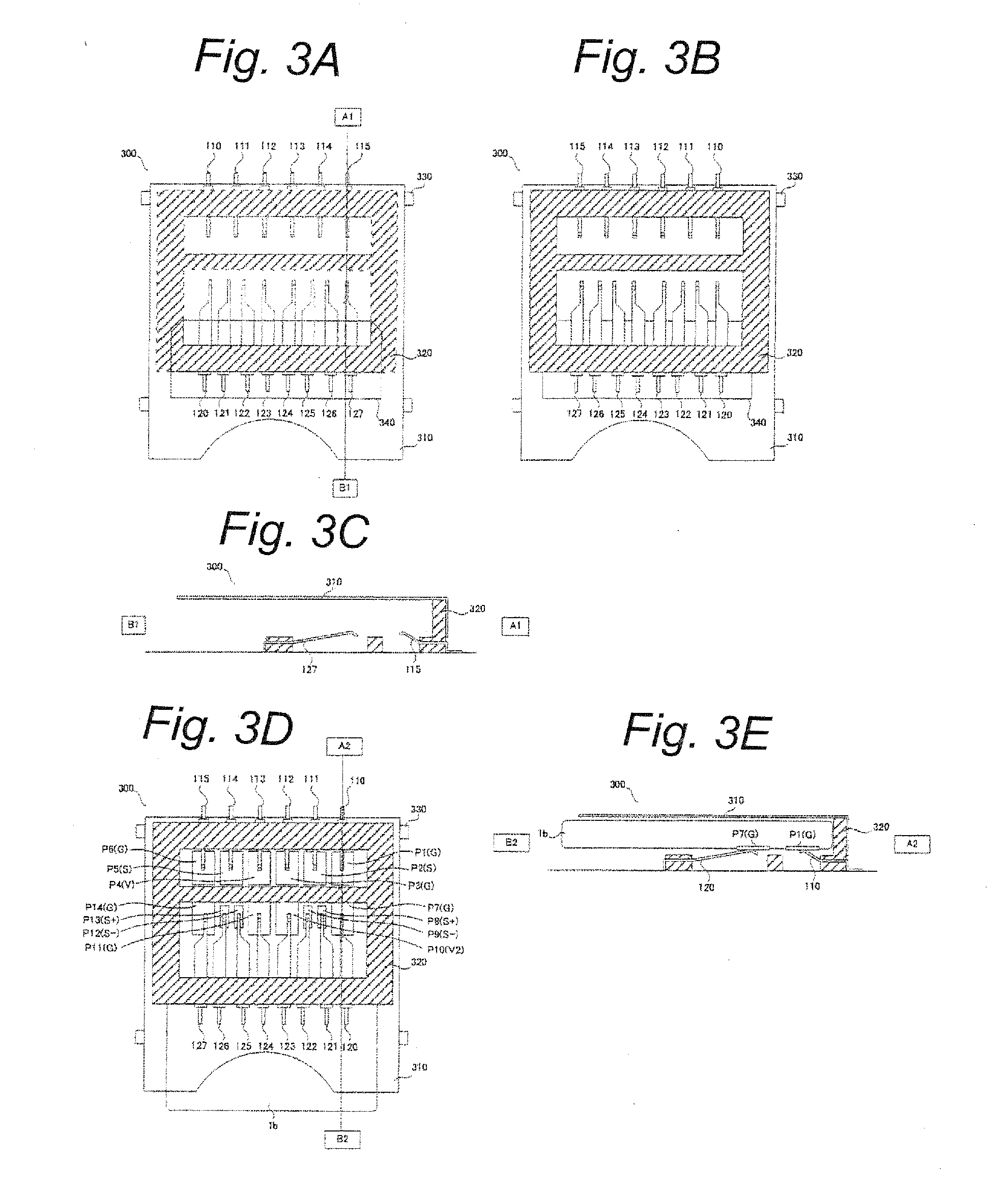
[0051]FIG. 4A to FIG. 4E are schematic diagrams illustrating a configuration of a memory card socket 400 according to an embodiment 1. Specifically, FIG. 4A is a top view of the memory card socket 400, and dotted and dashed lines illustrate a transparent view covered under a cover shell 310. Further, FIG. 4B is a rear view of the memory card socket 400. An upper view of FIG. 4C is a cross-sectional view taken along line A3-B3 in FIG. 4A, and a lower view of FIG. 4C is a cross-sectional view taken along line A3′-B3′ in FIG. 4A. FIG. 4D is a schematic diagram when the memory card 1b including the differential transmission pins for high-speed signal transmission, and the stable potential pins of different potentials and adjacently provided on left and right side of the differential pair pins is inserted. An upper view of FIG. 4E is a cross-sectional view taken along line A4-B4 in FIG. 4D, and a lower view of FIG. 4E is a cross-sectional view taken along line A4′-B4′ in FIG. 4D.
[0052]Th...
PUM
 Abstract
Description
Claims
Application Information
 - R&D
- Intellectual Property
- Life Sciences
- Materials
- Tech Scout
- Unparalleled Data Quality
- Higher Quality Content
- 60% Fewer Hallucinations
Browse by: Latest US Patents, China's latest patents, Technical Efficacy Thesaurus, Application Domain, Technology Topic, Popular Technical Reports.
© 2025 PatSnap. All rights reserved.Legal|Privacy policy|Modern Slavery Act Transparency Statement|Sitemap|About US| Contact US: help@patsnap.com


