Spinal fixation system

a fixation system and spine technology, applied in the field of orthopedic surgery, can solve the problems of reducing nerve function, affecting the treatment effect and affecting the recovery of patients,

Active Publication Date: 2013-02-21
K2M
View PDF9 Cites 106 Cited by
  • Summary
  • Abstract
  • Description
  • Claims
  • Application Information

AI Technical Summary

Benefits of technology

[0011]The present disclosure is directed to a polyaxial pedicle screw including a housing, a bone screw member, and an anvil. The bone screw member is selectively positionable at a plurality of angles relative to the housing when engaged to the housing and securable relative to the housing at a cone angle of up to approximately 80 degrees. The bone screw member includes a head and a threaded shaft extending from the head. The head is selectively securable within the housing. The head may include surface texture that frictionally engages with the anvil such that a user applied force is necessary to reposition the bone screw member relative to the anvil when the bone screw member is disposed in engagement with the anvil. The head of the bone screw member includes a first portion and a second portion. Only one of the first and second portions enable the head to fit through an opening defined in the housing and the other of the first and second portions maintains the head of the bone screw member within the housing once inserted. One of the first and second portions may be cylindrically shaped and the other of the first and second portions may be spherically shaped. The cylindrically shaped portion enables the head to fit through the opening in the housing in an insertion orientation of the screw head relative to the housing, and the spherically shaped portion maintains the head of the bone screw member within the housing once inserted and moved away from the insertion orientation.

Problems solved by technology

Persons suffering from any of the above conditions typically experience extreme or debilitating pain and often times diminished nerve function.
These conditions and their treatments can be further complicated if the patient is suffering from osteoporosis, or bone tissue thinning and loss of bone density.
However, when large deformity corrections are necessary these rods are not always strong enough.
In addition, in order to reduce the likelihood of material incompatibility in vivo, the screw assembly also needs to be made of stainless steel to match the rod material, which is not a cost effective alternative.

Method used


Image

  • Spinal fixation system
  • Spinal fixation system
  • Spinal fixation system

Examples


Embodiment Construction

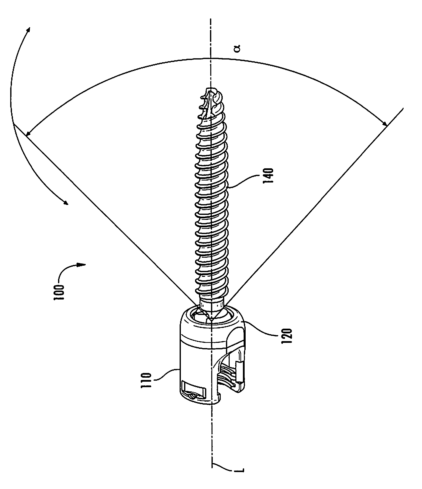
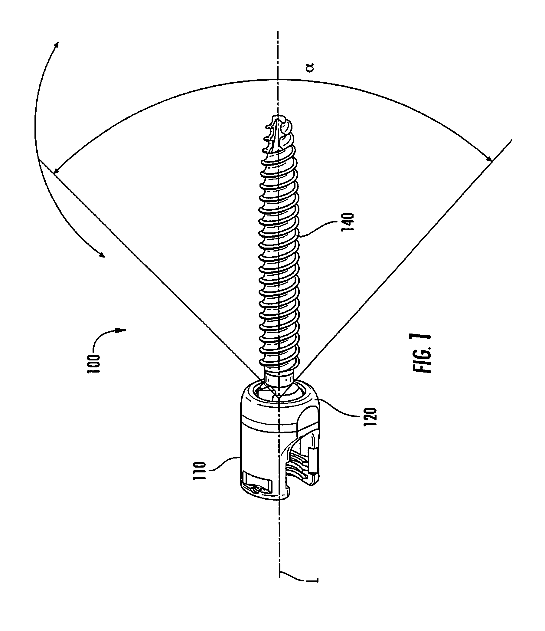
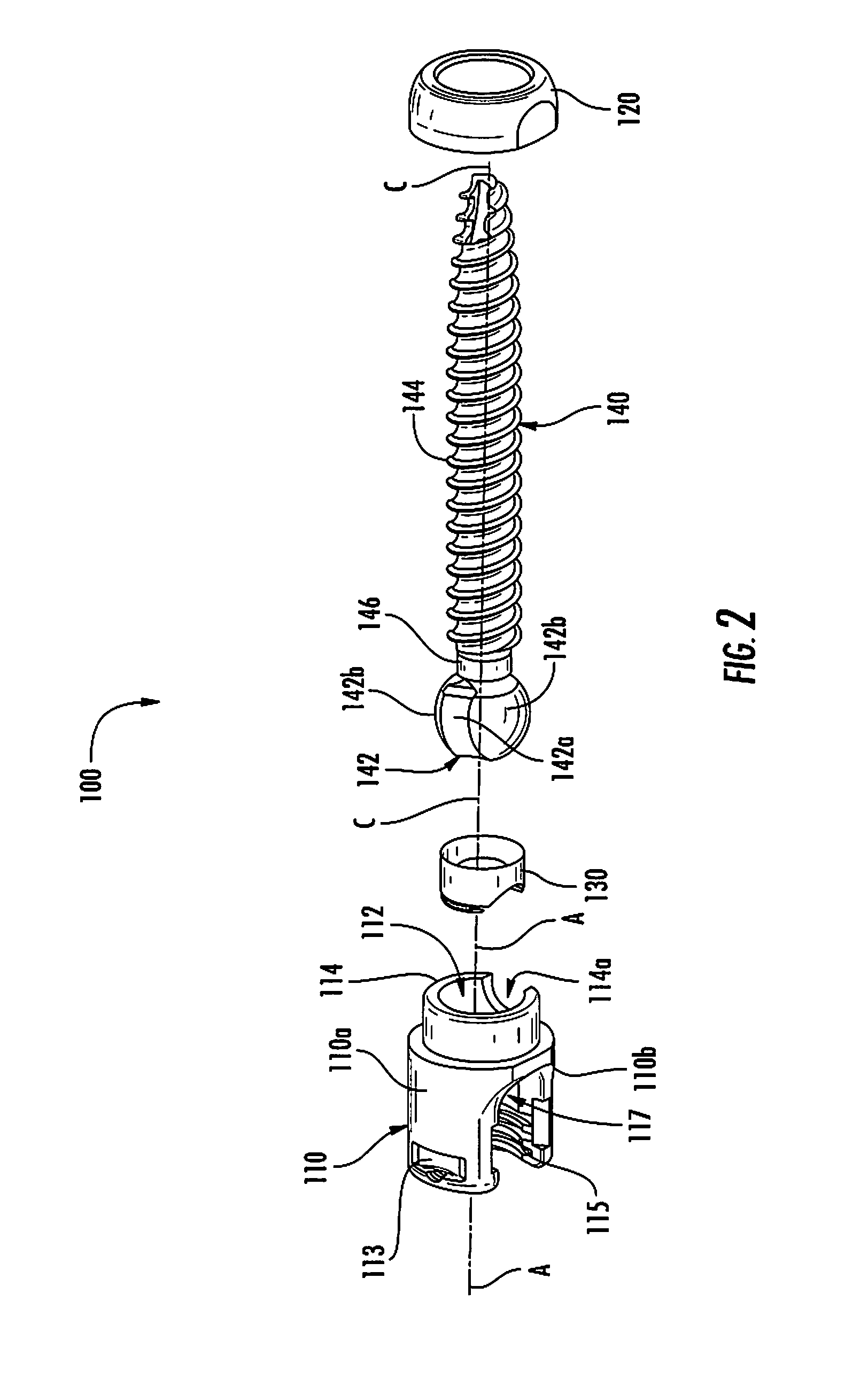
[0069]Particular embodiments of the present disclosure will be described herein with reference to the accompanying drawings. As shown in the drawings and as described throughout the following description, and as is traditional when referring to relative positioning on an object, the terms “proximal” and “trailing” may be employed interchangeably, and should be understood as referring to the portion of a structure that is closer to a clinician during proper use. The terms “distal” and “leading” may also be employed interchangeably, and should be understood as referring to the portion of a structure that is farther from the clinician during proper use. In addition, the term “cephalad” or “cranial” is used in this application to indicate a direction toward a patient's head, whereas the term “caudad” indicates a direction toward the patient's feet. Further still, the term “medial” indicates a direction toward the middle of the body of the patient, whilst the term “lateral” indicates a d...


PUM


Abstract

A polyaxial pedicle screw includes a housing, a bone screw member, and an anvil. The bone screw member includes a head and a threaded shaft extending from the head. The head is selectively securable within the housing. The anvil is positionable within the housing adjacent to the head of the bone screw member when the anvil and the head of the bone screw member are positioned within the housing. The anvil may define one or more grooves in an outer surface of the anvil. The groove defines a flap that is flexibly attached to the anvil to enable the anvil to flex an amount sufficient to maintain the head of the bone screw in constant contact with the anvil when the bone screw member is moved relative to the anvil. A rod reducer may be secured to the polyaxial pedicle screw to secure a spinal rod within the housing.

Description

CROSS REFERENCE TO RELATED APPLICATIONS[0001]This application is a continuation-in-part of U.S. patent application Ser. No. 13 / 214,331 filed Aug. 22, 2011 which claims priority to, and the benefit of, U.S. Provisional Patent Application Ser. No. 61 / 375,354 filed Aug. 20, 2010. The present application also claims priority to, and the benefit of, U.S. Provisional Patent Application Ser. No. 61 / 527,632 filed Aug. 26, 2011. The entire contents of each of these prior applications are incorporated by reference herein.BACKGROUND[0002]1. Technical Field[0003]The present disclosure relates generally to orthopedic surgery with particular regard to spinal surgery. Specifically, the present disclosure relates to spinal fixation systems.[0004]2. Description of Related Art[0005]The spinal column is a complex system of bones and connective tissues that provide support for the human body and protection for the spinal cord and nerves. The adult spine is comprised of an upper and lower portion. The u...

Claims


Application Information

Patent Timeline
Patent Type & Authority Applications(United States)
IPC IPC(8): A61B17/70A61B17/86A61B17/88
CPCA61B17/7037A61B2017/0046A61B17/8625A61B17/7086
Inventor JONES, SCOTTBOACHIE-ADJEI, OHENEBAMCCLINTOCK, LARRYSTRAUSS, KEVINCARBONE, JOHN
Owner K2M
Why Eureka
Try Eureka