
Electric fuel pump tester and method

a technology of electric fuel pump and tester device, which is applied in the direction of positive displacement liquid engine, machine/engine, instruments, etc., can solve the problems of laborious process of uninstalling the fuel pump from the vehicle, inability to quickly yet thoroughly test the electric, and inaccurate conclusions concerning the operability of the fuel pump, so as to achieve quick discernment and more accurate diagnosis of vehicular fuel system problems.

Inactive Publication Date: 2013-02-21
FEDERAL MOGUL MOTORPARTS LLC
View PDF12 Cites 5 Cited by
  • Summary
  • Abstract
  • Description
  • Claims
  • Application Information

AI Technical Summary

Benefits of technology

The present invention is a small and light test unit that can quickly determine if an electric fuel pump is working properly or if further testing is required. This invention provides a quick and initial assessment of fuel pump functionality, resulting in more accurate diagnosis of vehicular fuel system problems and fewer erroneous returns of electrical fuel pumps to their manufacturers.

Problems solved by technology

A common issue encountered when attempting to diagnose a problem with a vehicle's fuel system is that the technician is unable to quickly yet thoroughly test the electric fuel pump so as to either identify it as the problem or to rule it out.
In some cases, this was accompanied by the laborious process of uninstalling the fuel pump from the vehicle.
This approach often lead to an erroneous conclusion concerning the operability of the fuel pump.
In many reported cases, technicians using this simple voltage test have mistakenly replaced the fuel pump in a vehicle multiple times without realizing that the fuel pumps were never defective but instead the electrical system of the vehicle was the root cause of the problem.
In each of these instances, substantial additional cost and inconvenience is caused to the vehicle owner, pump manufacturer and / or service technician due to the misdiagnosis.

Method used


Image

  • Electric fuel pump tester and method
  • Electric fuel pump tester and method
  • Electric fuel pump tester and method

Examples


Embodiment Construction

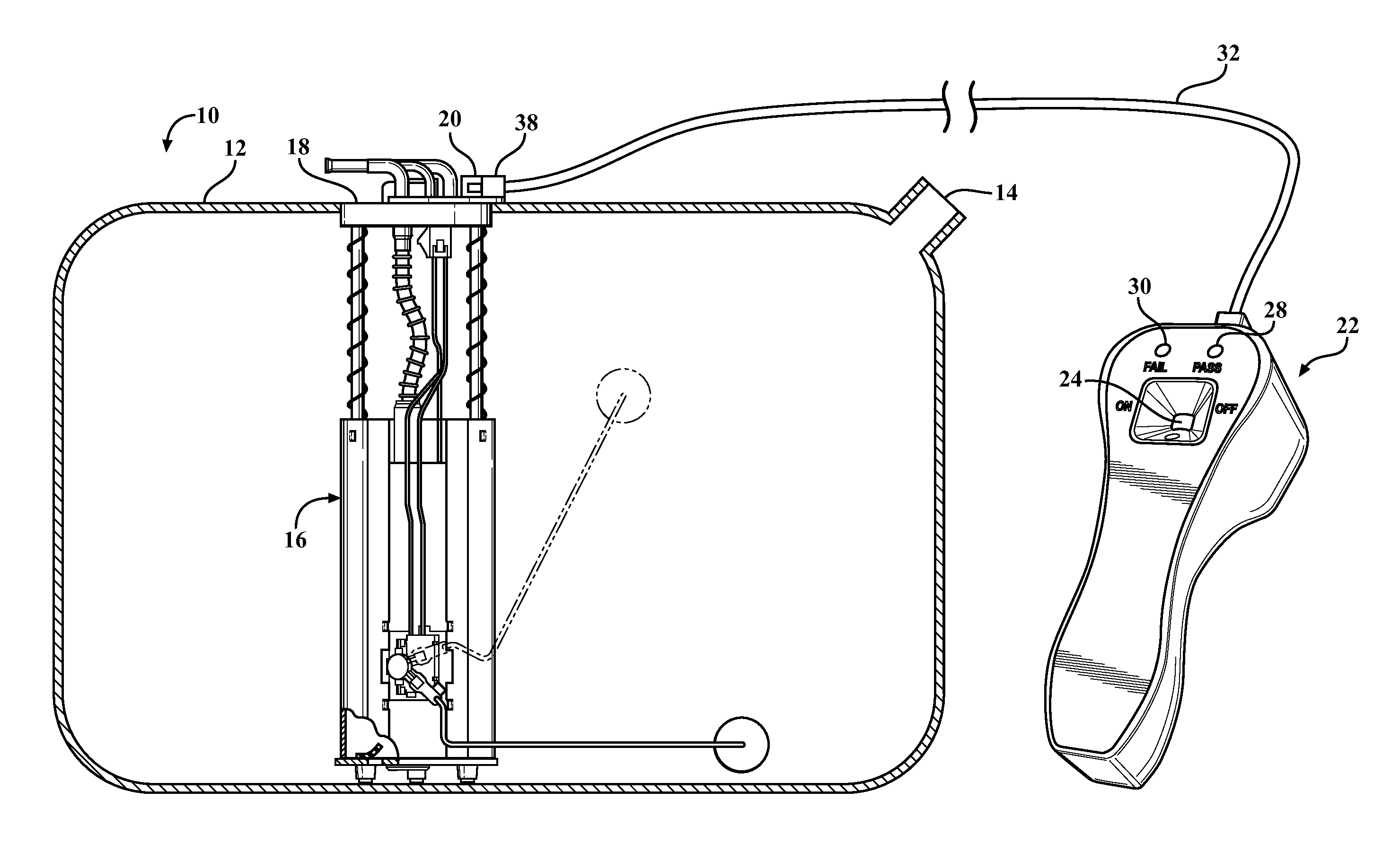
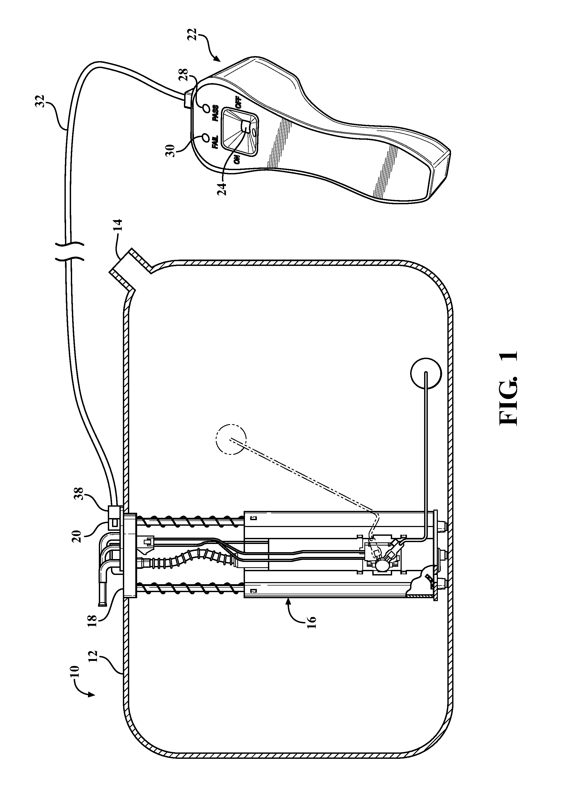
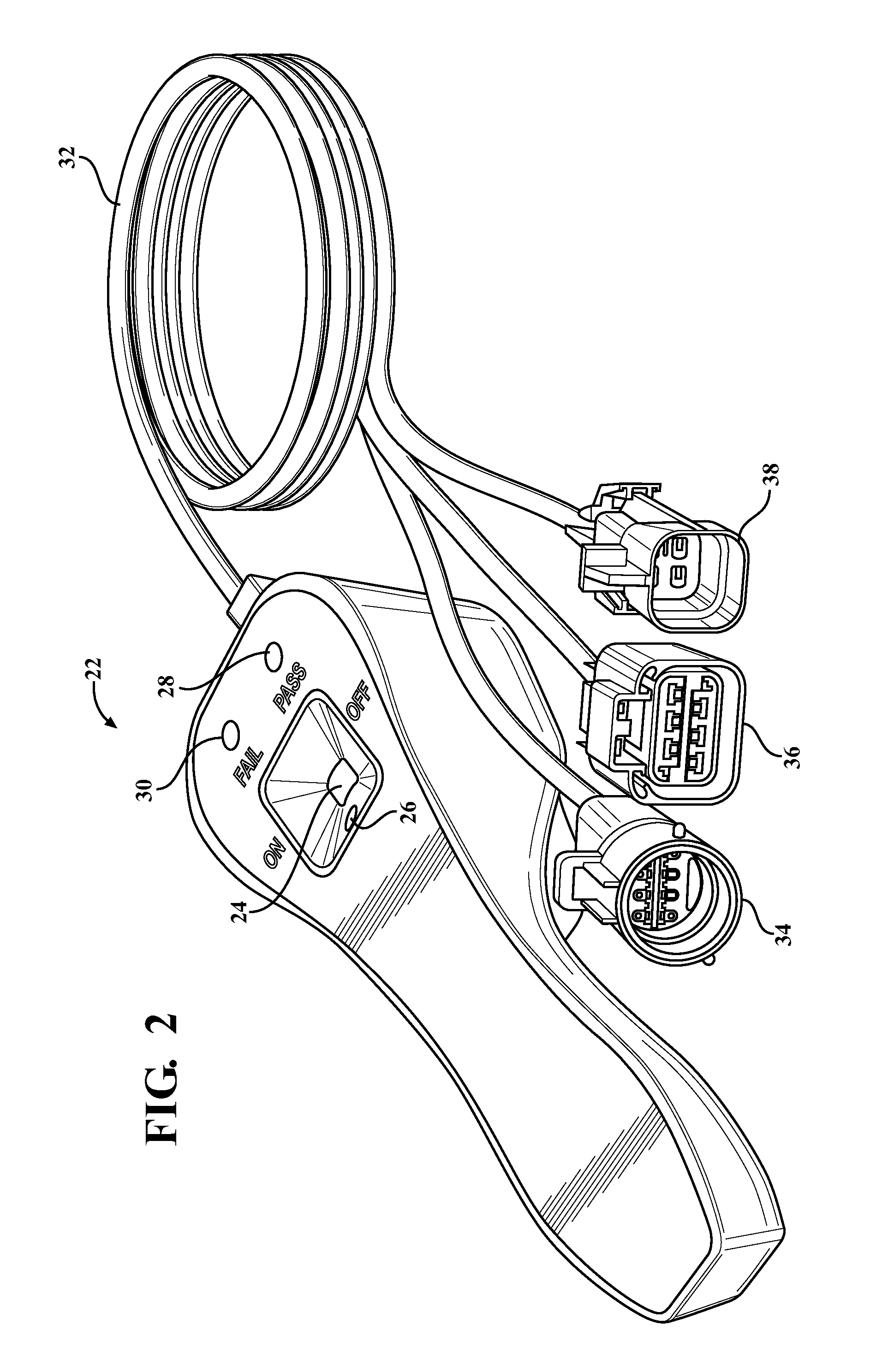
[0020]Referring to the figures, wherein like numerals indicate like or corresponding parts throughout the several views, the present invention provides a system and method for testing the real-life electrical operating characteristics of a vehicle's fuel pump. A portion of a vehicular fuel system is generally shown at 10 in FIG. 1. In this example, the fuel system 10 includes a tank assembly 12 of the type commonly used for containing liquid fuel, such as gasoline, and then supplying that fuel upon demand to an internal combustion engine (not shown). The tank assembly 12 in this example comprises a thin-walled, hollow member into which liquid fuel is filled through a nozzle 14. An electric fuel pump module, generally indicated at 16, is disposed in the tank. This example depicts the fuel pump 16 as an in-tank type combined within a module assembly including a float, filter and other features. However, the principles of this invention can be applied equally to stand-alone fuel pumps,...


PUM


Abstract

The system and method for determining the operational condition of an electric fuel pump (16). The test apparatus (22) is configured to perform first, second and third tests. During the first test, a low voltage, low current signal is applied to produce an inductive reflectance from the pump armature winding. During the second test, continuity is assessed in the coil winding circuit. During the third test, a higher power, short duration pulse is applied to create rotational movement of the pump armature for the purpose of detecting mechanical and / or electrical issues not otherwise discerned from the prior tests. An optional fourth test may be conducted in which the pump (16) is run for a short period of time at standard operating power to generate a current waveform. Collected test data is compared to stored reference data sets using a processor contained within the test apparatus (22). If collected test data corresponds within an acceptable threshold range to the reference data, a PASS signal is generated.

Description

CROSS REFERENCE TO RELATED APPLICATIONS[0001]None.BACKGROUND OF THE INVENTION[0002]1. Field of the Invention[0003]This invention relates generally to method for fault detecting in electric components located in vehicle circuits and, more particularly, to a tester device and testing method for testing the electrical operating characteristics of an electric fuel pump.[0004]2. Related Art[0005]When a vehicle's fuel system is malfunctioning, the electric fuel pump is often considered first to determine whether it is defective. A common issue encountered when attempting to diagnose a problem with a vehicle's fuel system is that the technician is unable to quickly yet thoroughly test the electric fuel pump so as to either identify it as the problem or to rule it out. According to most prior art techniques, a technician would test the voltage at the fuel pump electrical connection on the vehicle wire harness. In some cases, this was accompanied by the laborious process of uninstalling the ...

Claims


Application Information

Patent Timeline
IPC IPC(8): G01M13/00G01R31/72
CPCF04B17/03F04D5/002F04B51/00F04D27/001G01R31/2829G01R31/007G01R31/024G01R31/06G01R31/34G01R31/72G01R31/54
Inventor MCGAUGHEY, ROBERT J.
Owner FEDERAL MOGUL MOTORPARTS LLC
Learn More