Control apparatus for temperature excursions within an exhaust gas treatment system

a technology of control apparatus and exhaust gas treatment system, which is applied in the direction of mechanical apparatus, engine components, machines/engines, etc., can solve the problems of temperature excursion that can damage the filter substrate, sudden reduction of the exhaust gas flow rate through the regenerating filter, etc., and achieve the effect of increasing the volumetric gas flow ra

Inactive Publication Date: 2013-02-28
GM GLOBAL TECH OPERATIONS LLC
View PDF6 Cites 15 Cited by
  • Summary
  • Abstract
  • Description
  • Claims
  • Application Information

AI Technical Summary

Benefits of technology

[0007]In an exemplary embodiment of the invention, an exhaust gas treatment system for an internal combustion engine comprises an exhaust gas conduit in fluid communication with, and configured to receive exhaust gas from, the internal combustion engine and a particulate filter assembly in fluid communication with the exhaust gas conduit and configured to receive exhaust gas flowing therethrough. The particulate filter assembly comprises an electrically heated catalyst, a particulate filter disposed downstream of the electrically heated catalyst to remove particulate material from the exhaust gas, a hydrocarbon injector in fluid communication with the exhaust gas conduit upstream of the electrically heated catalyst and configured to inject excess hydrocarbon into the exhaust gas flowing therethrough, an air pump in fluid communication with the exhaust gas conduit upstream of the electrically heated catalyst and configured to deliver air to the exhaust gas conduit to increase the volumetric gas flow rate through, and to decrease the heat residence time in, the particulate filter and a controller configured to operate the hydrocarbon injector, the electrically heated catalyst and the air pump based on predetermined exhaust gas flow rates, temperature thresholds and particulate loadings within the particulate filter.
[0008]In another exemplary embodiment of the invention a method for regenerating a particulate filter assembly in an exhaust system of an internal combustion engine having an exhaust gas conduit in fluid communication with, and configured to receive exhaust gas from, the internal combustion engine, the particulate filter assembly in fluid communication with the exhaust gas conduit and configured to receive exhaust gas flowing therethrough, the particulate filter assembly comprising an electrically heated catalyst, a catalytic converter downstream of the electrically heated catalyst, a particulate filter disposed downstream of the catalytic converter to remove particulate material from the exhaust gas, a hydrocarbon injector in fluid communication with the exhaust gas conduit upstream of the electrically heated catalyst and configured to inject excess hydrocarbon into the exhaust gas flowing therethrough, an air pump in fluid communication with the exhaust gas conduit upstream of the electrically heated catalyst and configured to deliver air to the exhaust gas conduit to increase the volumetric gas flow rate and decrease the heat residence time through the particulate filter and a controller configured to operate the hydrocarbon injector, the electrically heated catalyst and the air pump based on predetermined exhaust gas flow rates, temperature thresholds and particulate loadings within the particulate filter comprises heating the electrically heated catalyst to a hydrocarbon oxidation temperature, activating the hydrocarbon injector to deliver excess hydrocarbon into the exhaust gas, oxidizing the excess hydrocarbon in the electrically heated catalyst to raise the temperature of the exhaust gas and to oxidize particulates in the particulate filter, monitoring the exhaust gas flow rate, monitoring the temperature of the particulate filter, and deactivating the electrically heated catalyst and the hydrocarbon injector and activating the air pump when the exhaust flow rate through the particulate filter drops below a predetermined flow rate threshold or the temperature of the particulate filter is above a predetermined temperature threshold, or both.

Problems solved by technology

There are certain control issues associated with exhaust gas filter regeneration.
This condition may result is a sudden reduction of the exhaust gas flow rate through the regenerating filter.
Upon a sudden reduction in exhaust flow through the regenerating filter, the heat generated by the oxidation of the accumulated particulates accumulates in the particulate filter (i.e. the exhaust gas flow rate is insufficient to remove the heat from the oxidizing particulates) and may lead to a temperature excursion that can be damaging to the filter substrate.

Method used


Image

  • Control apparatus for temperature excursions within an exhaust gas treatment system
  • Control apparatus for temperature excursions within an exhaust gas treatment system
  • Control apparatus for temperature excursions within an exhaust gas treatment system

Examples


Embodiment Construction

[0013]The following description is merely exemplary in nature and is not intended to limit the present disclosure, its application or uses. It should be understood that throughout the drawings, corresponding reference numerals indicate like or corresponding parts and features.

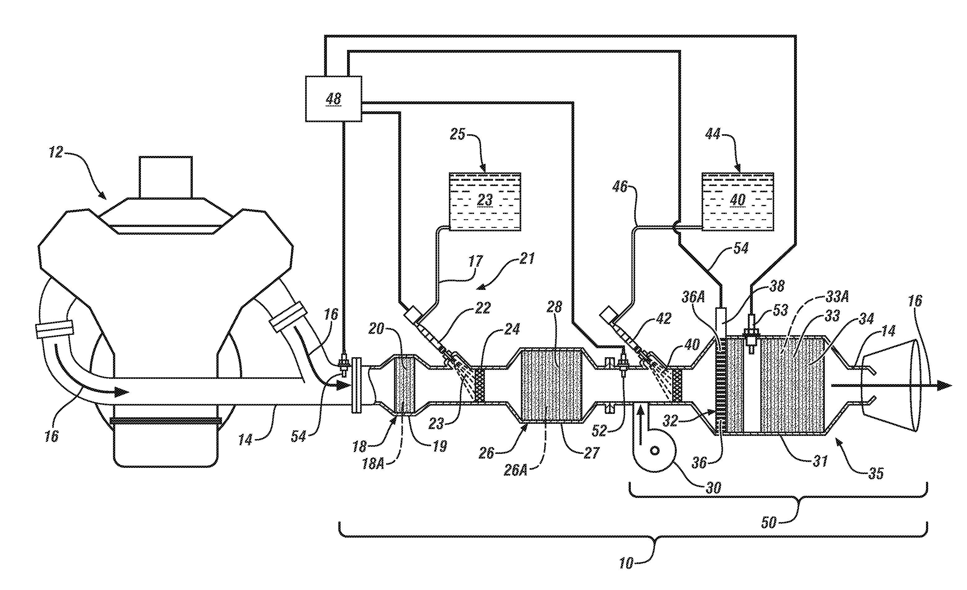
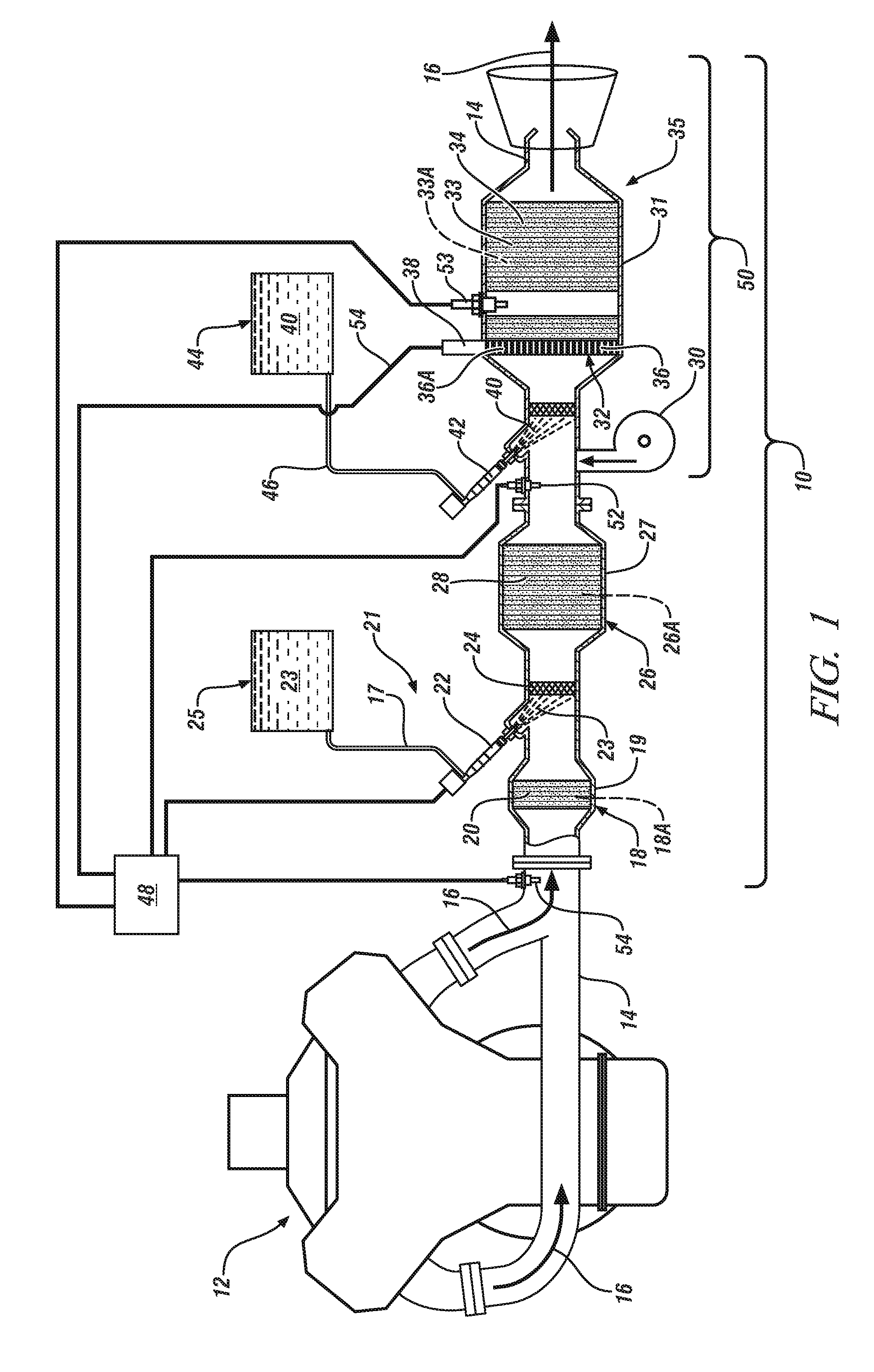
[0014]Referring now to FIG. 1, an exemplary embodiment of the invention is directed to an exhaust gas treatment system, referred to as 10, for the reduction of regulated exhaust gas constituents of an internal combustion engine 12. It can be appreciated that the invention described herein can be implemented in various engine systems implementing an exhaust gas particulate filter. Such engine systems may include, but are not limited to, diesel engines, gasoline direct injection systems and homogeneous charge compression ignition engine systems.

[0015]The exhaust gas treatment system 10 includes an exhaust gas conduit 14, which may comprise several segments, that is in fluid communication with and is configured to...


PUM


Abstract

An exhaust gas treatment system for an internal combustion engine comprises a particulate filter assembly configured to receive exhaust gas from the engine. The particulate filter assembly comprises an electrically heated catalyst, a particulate filter disposed downstream of the electrically heated catalyst, a hydrocarbon injector, in fluid communication with the exhaust gas, upstream of the electrically heated catalyst and configured to inject excess hydrocarbon into the exhaust gas, an air pump in fluid communication with the exhaust gas upstream of the electrically heated catalyst and configured to deliver air to the exhaust gas to increase the volumetric gas flow rate through, and to decrease the heat residence time in, the particulate filter and a controller configured to operate the hydrocarbon injector, the electrically heated catalyst and the air pump based on predetermined exhaust gas flow rates, temperature thresholds and particulate loadings within the particulate filter.

Description

FIELD OF THE INVENTION[0001]Exemplary embodiments of the invention relate to exhaust gas treatment systems for internal combustion engines and, more particularly, to a method of reducing temperature excursions during the regeneration of an exhaust gas particulate filter.BACKGROUND[0002]The exhaust gas emitted from an internal combustion engine is a heterogeneous mixture that may contain gaseous emissions such as carbon monoxide (“CO”), unburned hydrocarbons (“HC”) and oxides of nitrogen (“NOx”) as well as condensed phase materials (liquids and solids) that constitute particulate matter (“PM”). Catalyst compositions typically disposed on catalyst supports or substrates are provided in an engine exhaust system to convert certain, or all of these exhaust constituents into non-regulated exhaust gas components.[0003]In the realm of exhaust treatment technologies, there are several known filter structures that have displayed effectiveness in removing particulate matter from the exhaust ga...

Claims


Application Information

Patent Timeline
Patent Type & Authority Applications(United States)
IPC IPC(8): F01N3/035F01N3/18F01N3/36
CPCF01N3/2013F01N3/225F01N9/002F01N3/0253F01N3/035F01N2560/06F01N3/323Y02T10/26Y02T10/47F01N3/02F01N3/021F01N3/023F01N2560/07Y02T10/12Y02T10/40
Inventor GONZE, EUGENE V.PARATORE, JR., MICHAEL J.BHATIA, GARIMA
Owner GM GLOBAL TECH OPERATIONS LLC
Why Eureka
Try Eureka