Fluid management system

Inactive Publication Date: 2013-02-28
MILLER TIMOTHY E
View PDF17 Cites 24 Cited by
  • Summary
  • Abstract
  • Description
  • Claims
  • Application Information

AI Technical Summary

Benefits of technology

[0008]In concordance with the instant disclosure, a fluid management system that is easy for vehicle owne

Problems solved by technology

The known fluid management systems are inconvenient and difficult for a vehicle owner to use.
For example, replacement of vehicle fluids often requires the vehicle owner to drop off the vehicle at a vehicle service center, which can be time consuming and may deter the vehicle owner from changing the vehicle fluids as often as recommended.
Known fluid management systems also occupy an unnecessary and inefficient amount of space in vehicles by including separate conduits, and separate draining and supplying areas.
Additionally, typical fluid management syste

Method used


Image

  • Fluid management system
  • Fluid management system
  • Fluid management system

Examples


Embodiment Construction

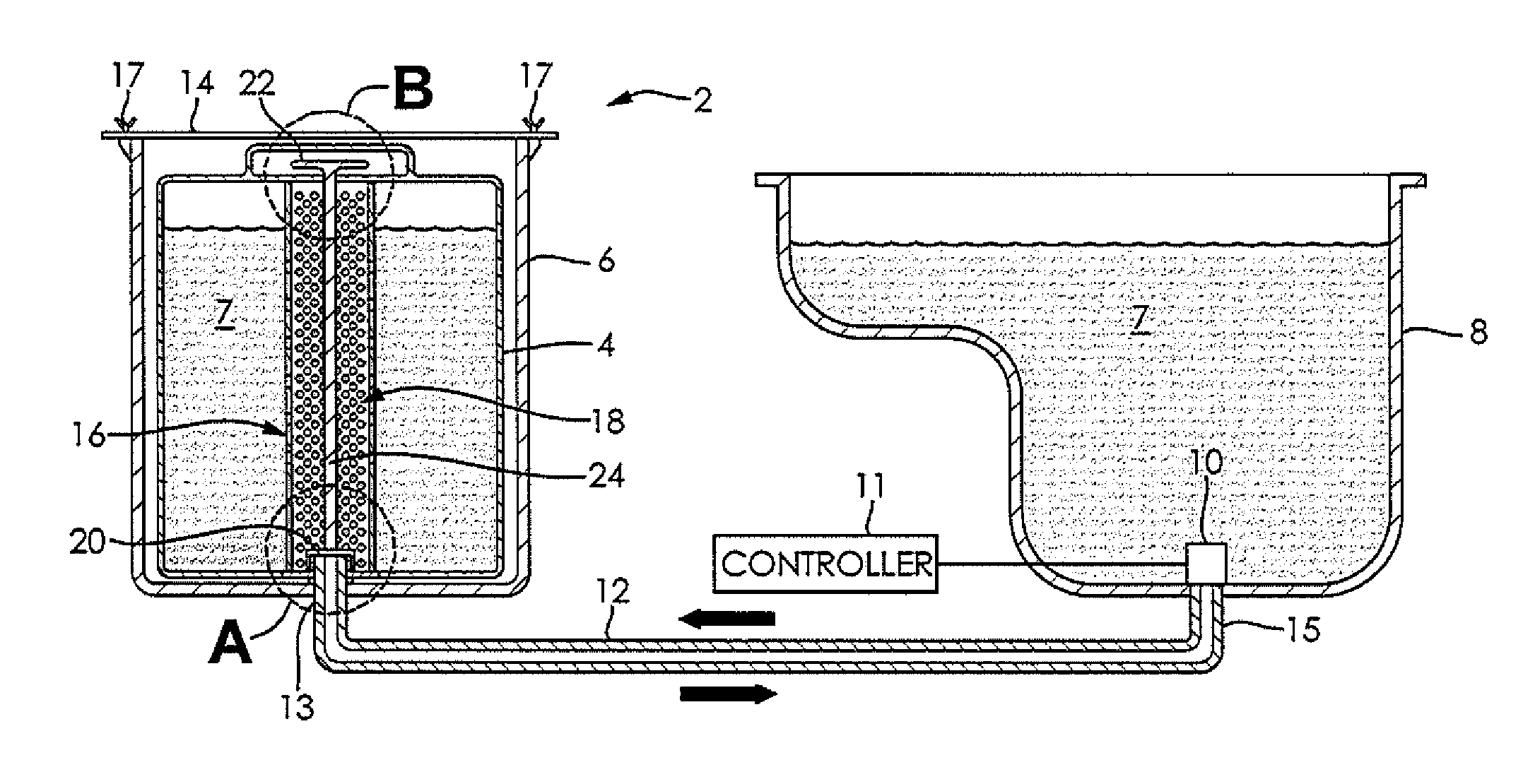
[0027]The following detailed description and appended drawings describe and illustrate various exemplary embodiments of the invention. The description and drawings serve to enable one skilled in the art to make and use the invention, and are not intended to limit the present disclosure, application, or uses. In respect of the methods disclosed, the order of the steps presented is exemplary in nature, and thus, is not necessary or critical.

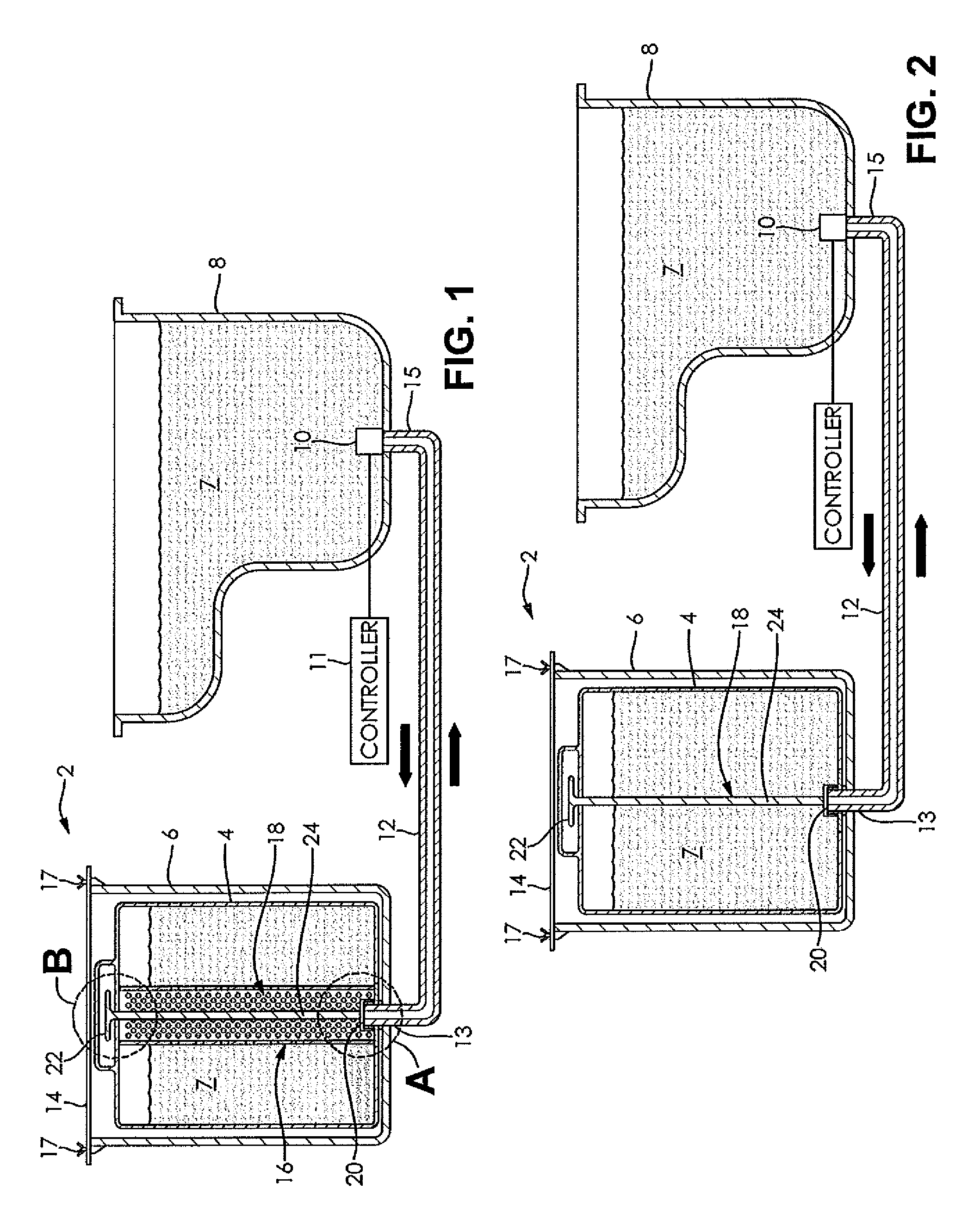
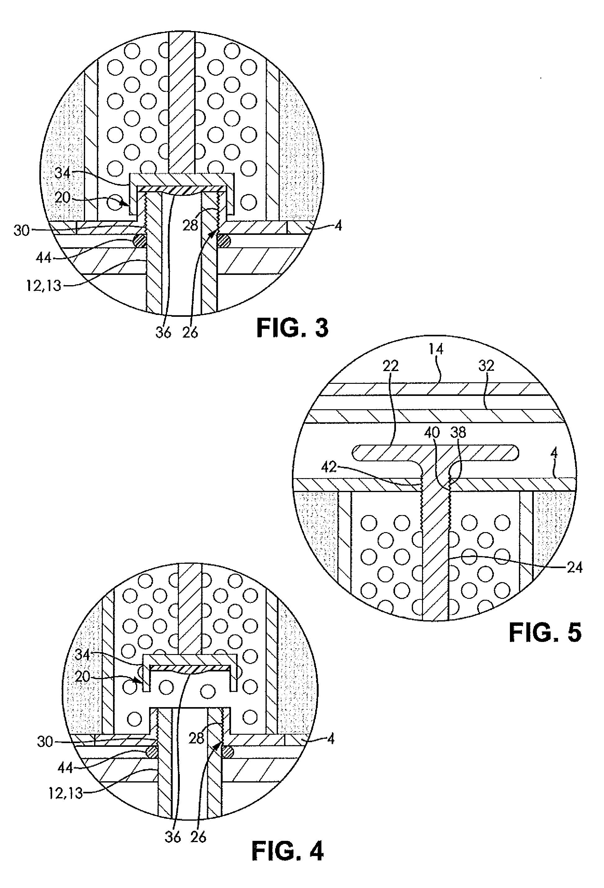
[0028]FIGS. 1-8 illustrate a fluid management system 2 for a vehicle, according to various embodiments of the present disclosure. FIGS. 1-5 show the fluid management system 2 employed with an oil pan of the vehicle. FIG. 6 shows the fluid management system 2 employed with a transmission of the vehicle. FIG. 7 shows the fluid management system 2 employed with a radiator of the vehicle. FIG. 8 shows the vehicle have each of the fluid management system 2 for each of the oil plan, the transmission, and the radiator of the vehicle.

[0029]As nonlimiting e...


PUM

PropertyMeasurementUnit
Flow rateaaaaaaaaaa
Diameteraaaaaaaaaa

Abstract

A fluid management system and a method for managing fluid include a removable cartridge, a fluid reservoir, a fluid exchange pump, and a conduit. The conduit provides fluid communication between the removable cartridge and the fluid reservoir. The fluid exchange pump transfers a first fluid from the fluid reservoir to the removable cartridge in a first direction, and permits a flow of a second fluid from the removable cartridge to the fluid reservoir in a second direction.

Description

CROSS-REFERENCE TO RELATED APPLICATIONS[0001]This application claims the benefit of U.S. Provisional Application No. 61 / 528,786, filed on Aug. 30, 2011. The entire disclosure of the above application is hereby incorporated herein by reference.FIELD OF THE INVENTION[0002]The present disclosure relates to a fluid management system and, more particularly, to a fluid management system for replacement of vehicle fluids.BACKGROUND OF THE INVENTION[0003]Fluid management systems in a vehicle are well known. Fluid management systems can be manual or automatic. Typically, fluid management systems have one conduit connected to an area for used fluids to drain into, and a separate conduit and area for introducing new fluids into the vehicle. As nonlimiting examples, U.S. Pat. Nos. 5,787,372, 6,286,626, 6,508,280, and 7,926,617 each disclose fluid management systems that include separate conduits and separate draining and supplying areas. The entire disclosures of each of the above-mentioned pat...

Claims


Application Information

Patent Timeline
IPC IPC(8): B60P3/22
CPCF01M11/0458B01D35/02F01M2011/0483F16H57/0408F16K24/00G05D7/0676Y10T137/0318Y10T137/6855Y10T137/794
Inventor MILLER, TIMOTHY E.
Owner MILLER TIMOTHY E
Why Eureka
Try Eureka