Camera, computer program and method for measuring thermal radiation and thermal rates of change

a technology of thermal radiation and thermal rate change, applied in the field of imaging cameras and image processing, can solve the problems of inaccuracy of thermal radiation detection and visual representation of standard thermal imaging cameras, and achieve the effect of improving image quality, reducing the probability of inaccuracy, and improving the accuracy of thermal radiation detection

Active Publication Date: 2013-02-28
PROGRESS RAIL SERVICES
View PDF2 Cites 38 Cited by
  • Summary
  • Abstract
  • Description
  • Claims
  • Application Information

AI Technical Summary

Benefits of technology

[0011]Additional embodiments of the present invention may provide for areas of interest within the camera's field of view to be detected and tracked. In such an embodiment, the camera may be attached to one or more servo-motors that operate to rotate the camera about one or more rotational axes. As areas of interest are detected, the locations of the area of interest may be calculated, and the camera operates to command the servo-motors to direct the camera in such a position that th

Problems solved by technology

However, standard thermal imaging cameras often have at least some inaccuracies in the detected IR and displayed visual rep

Method used


Image

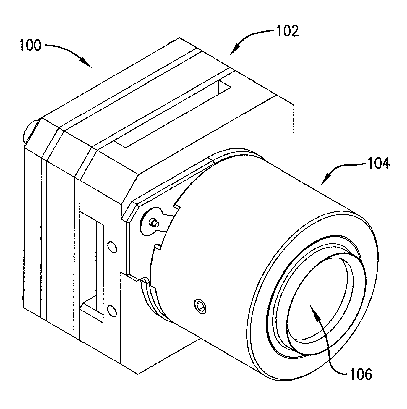
  • Camera, computer program and method for measuring thermal radiation and thermal rates of change
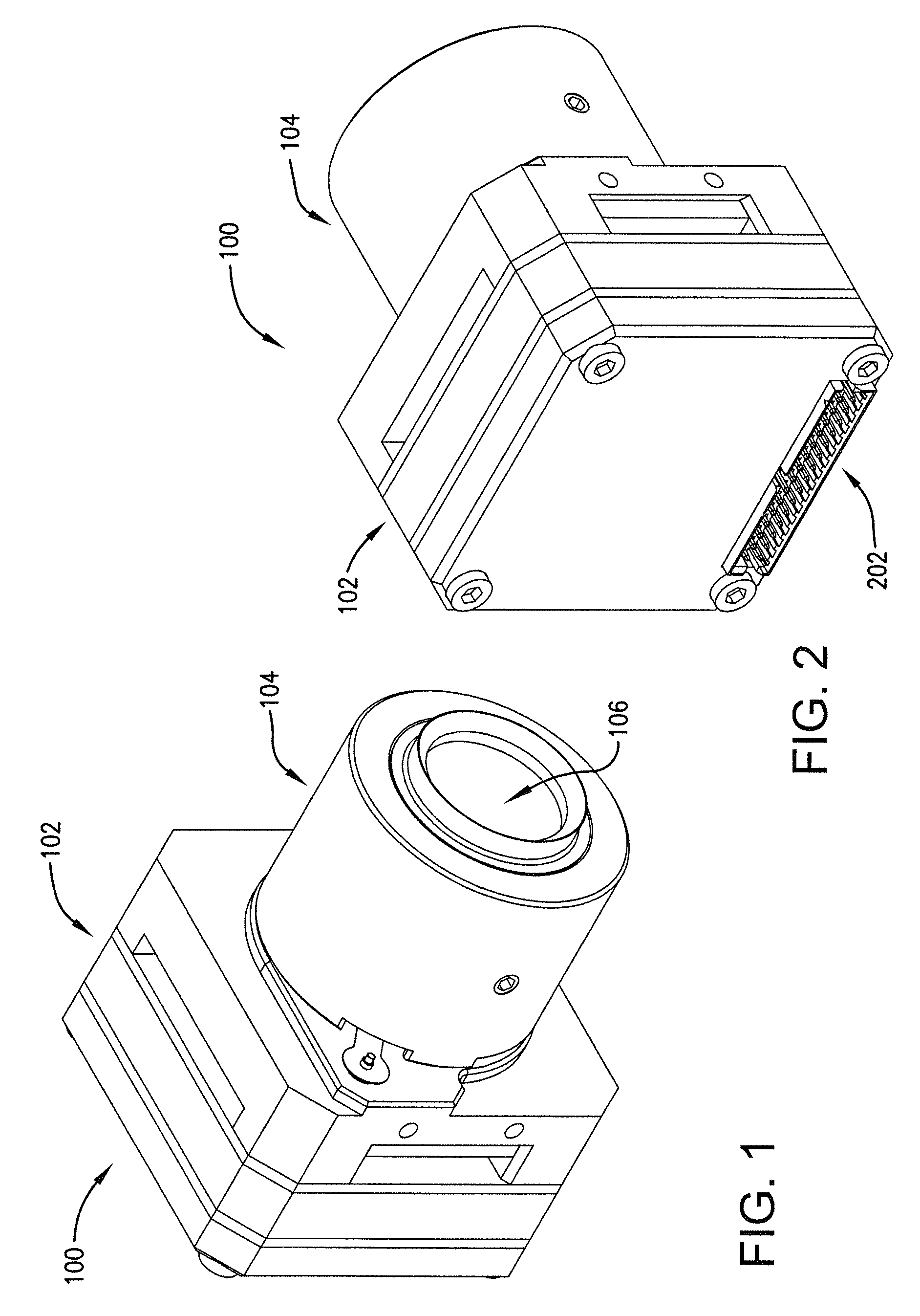
  • Camera, computer program and method for measuring thermal radiation and thermal rates of change
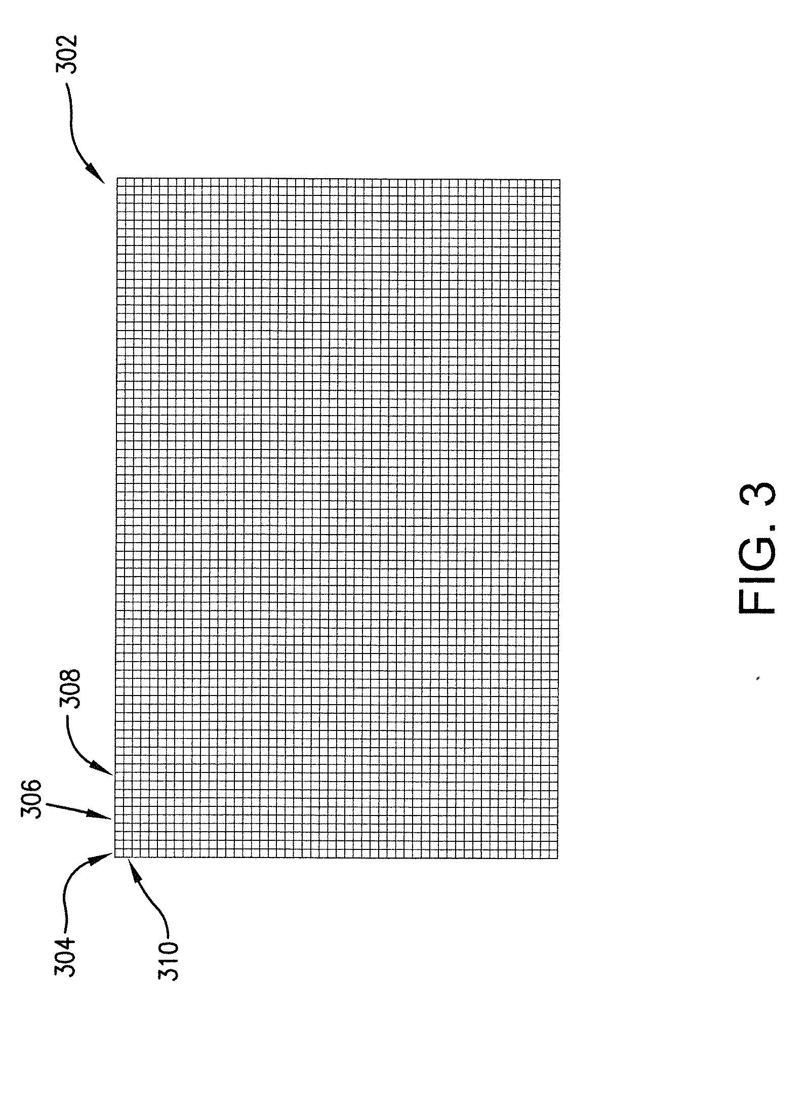
  • Camera, computer program and method for measuring thermal radiation and thermal rates of change

Examples


Embodiment Construction

[0029]The following detailed description of the invention references the accompanying drawings that illustrate specific embodiments in which the invention can be practiced. The embodiments are intended to describe aspects of the invention in sufficient detail to enable those skilled in the art to practice the invention. Other embodiments can be utilized and changes can be made without departing from the scope of the present invention. The following detailed description is, therefore, not to be taken in a limiting sense. The scope of the present invention is defined only by the appended claims, along with the full scope of equivalents to which such claims are entitled.

[0030]In this description, references to “one embodiment,”“an embodiment,” or “embodiments” mean that the feature or features being referred to are included in at least one embodiment of the technology. Separate references to “one embodiment,”“an embodiment,” or “embodiments” in this description do not necessarily refer...


PUM


Abstract

The present invention is directed to a camera, computer program, and method for determining and displaying temperature rates of change for objects within the camera's field of view. More specifically, the embodiments provide for the continuous, real-time temperature measurement and display of a plurality of objects within the camera's field of view, and further for the real-time processing and display of the temperature rates of change for said objects.

Description

RELATED APPLICATION[0001]This patent application claims priority benefit, with regard to all common subject matter, of earlier-filed U.S. Provisional Patent Application No. 61 / 527,724, filed Aug. 26, 2011, and entitled “THERMAL CURRENT DETECTION APPARATUS AND METHOD.” The identified earlier-filed provisional patent application is hereby incorporated by reference in its entirety into the present application.BACKGROUND[0002]1. Field[0003]Embodiments of the present invention are directed to the technical field of imaging cameras and image processing. More particularly, the embodiments are directed to a thermal and infrared imaging camera, computer program, and method for displaying visual representations of thermal scenes and for determining and displaying temperature rates of change for objects within the scenes.[0004]2. Related Art[0005]Thermal imaging systems, such as thermal cameras, are often employed in temperature and / or heat measurement applications. Objects with a temperature ...

Claims


Application Information

Patent Timeline
IPC IPC(8): G01J5/02
CPCH04N5/33G01J2005/0085G01J5/025G01J5/026G01J5/0025G01J5/20G01J5/62G01J2005/067G01J2005/0077G01J5/04G06T7/11G01J5/068G01J5/485G01J5/0805G01J2005/202G06T11/001
Inventor ABREO, GABRIEL G.
Owner PROGRESS RAIL SERVICES
Why Eureka
Try Eureka