
Image processing apparatus and method

a technology of image processing and image recovery, applied in the direction of picture signal generators, solid-state device signal generators, television systems, etc., can solve the problems of image quality degradation, inability to obtain proper image, and image quality degradation, so as to reduce false colors and reduce the load of image recovery processing

Active Publication Date: 2013-02-28
CANON KK
View PDF4 Cites 35 Cited by
  • Summary
  • Abstract
  • Description
  • Claims
  • Application Information

AI Technical Summary

Benefits of technology

The patent text reduces false colors in RAW images and reduces the workload on image recovery processing.

Problems solved by technology

When an object is sensed and imaged by a digital camera, the obtained image suffers from a degree of degradation in quality.
The degradation in image quality is caused particularly by the aberrations of the optical imaging system used to image the object.
An actual image, however, includes noise components.
In general, therefore, a proper image cannot be obtained.
This leads to a decrease in focal depth.
This leads to a considerable increase in the processing load of image recovery processing.
Therefore, using a pixel interpolation algorithm designed to suppress the generation of false colors cannot suppress false colors generated via image recovery processing.

Method used


Image

  • Image processing apparatus and method
  • Image processing apparatus and method
  • Image processing apparatus and method

Examples


first embodiment

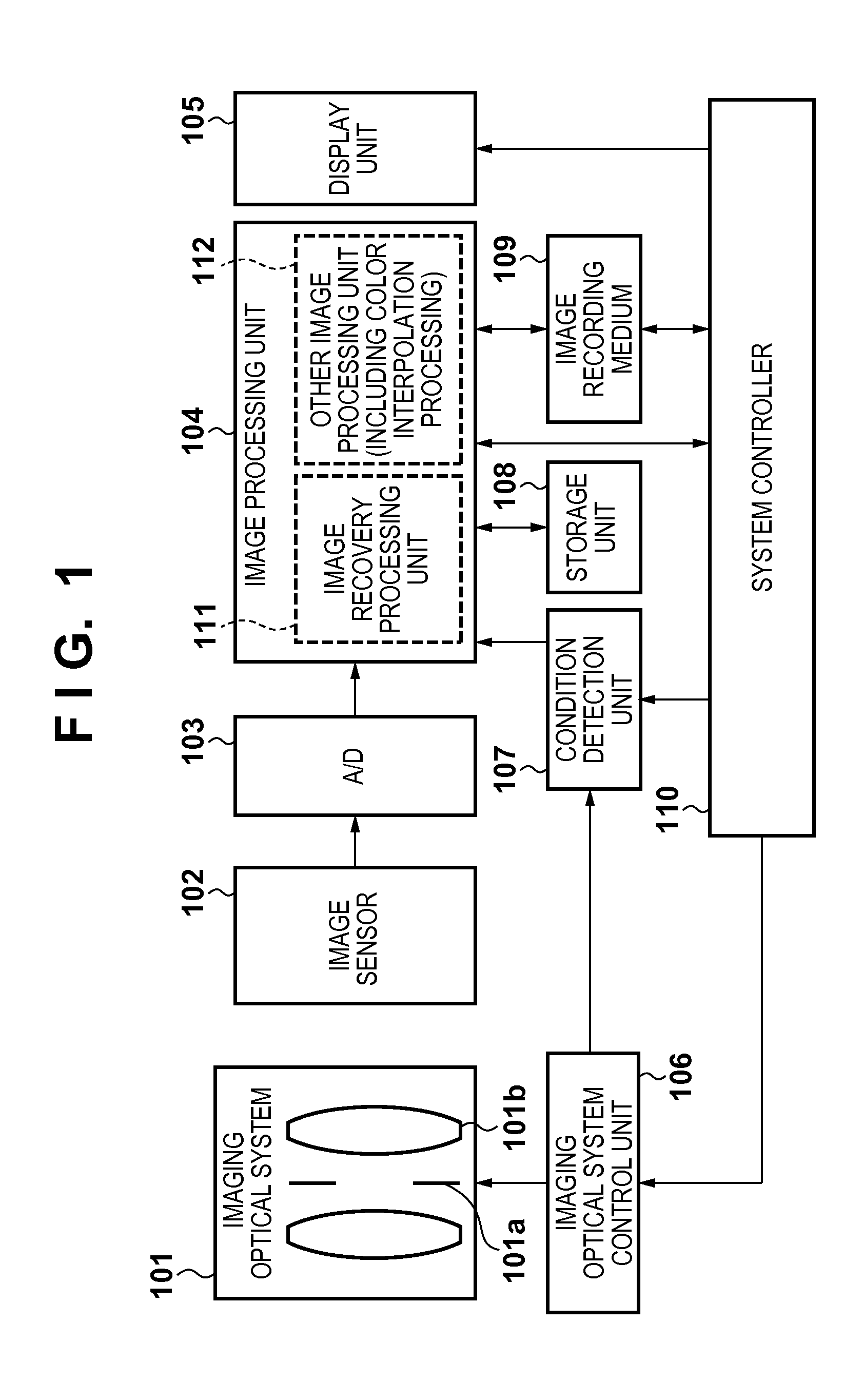
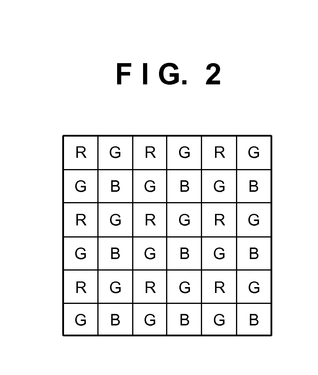
[0042]FIG. 1 shows an example of the basic arrangement of an image sensing apparatus according to an embodiment of the present invention. An object image (not shown) is incident on an image sensor 102 through an optical imaging system 101 which includes a stop 101a and a focus lens 101b. The image sensor 102 is covered with, for example, color filters arranged in a so-called Bayer arrangement shown in FIG. 2. Each pixel constituting the image sensor 102 outputs a signal of a color component corresponding to the color of a filter, of the red (R), green (G), and blue (B) color filters, with which the pixel is covered. The image sensor 102 converts image forming light into an electrical signal. An A / D converter 103 converts the signal into a digital signal and inputs it to an image processing unit 104. The image processing unit 104 constitutes an image recovery processing unit 111 and the other image processing unit 112 which performs predetermined processing. The image processing unit...

second embodiment

[0092]Image recovery processing according to the second embodiment of the present invention will be described below. Since the basic arrangement of an image capture apparatus according to the second embodiment is the same as that of the first embodiment shown in FIG. 1, a description of it will be omitted.

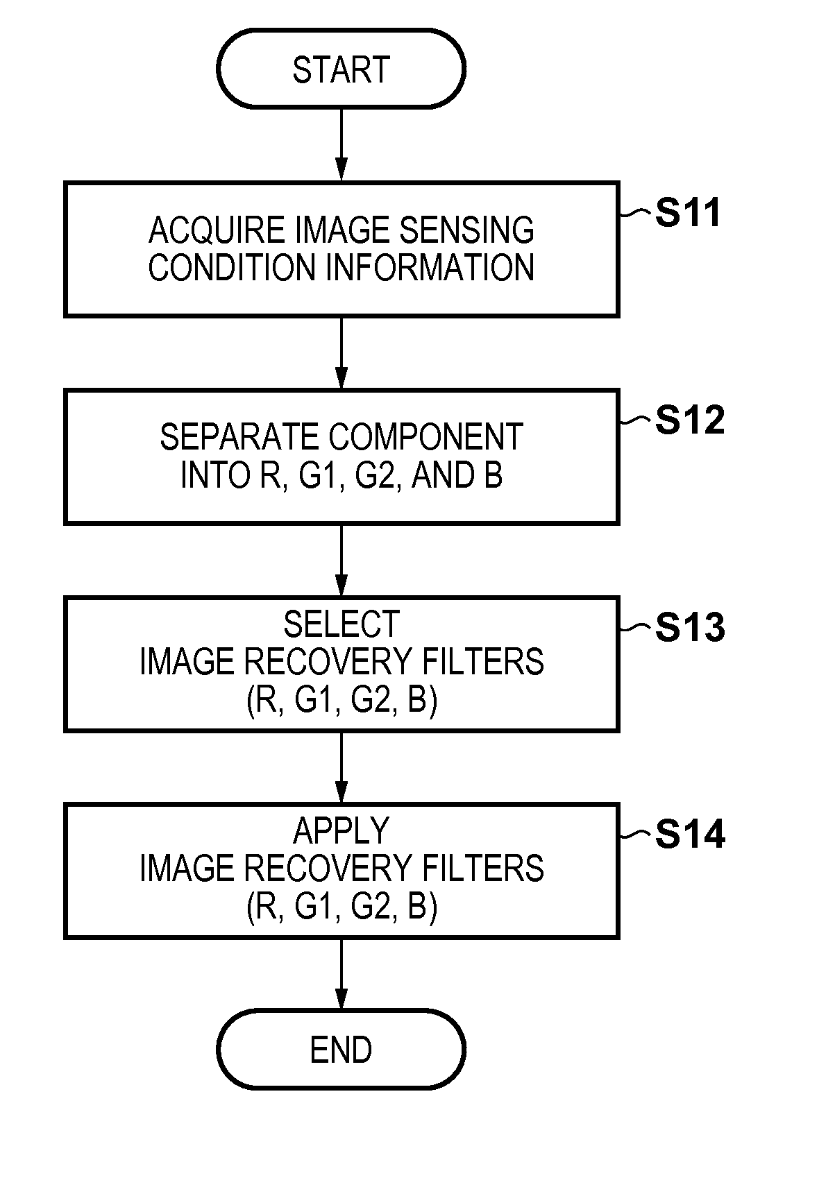
[0093]FIG. 13 shows the arrangement of an image processing unit 104 in the second embodiment. The image input to an image recovery processing unit 111 is RAW data with each pixel having a color component of one color of R, G, and B in the Bayer arrangement shown in FIG. 2. The second embodiment applies an image recovery filter to each input RAW data in a Bayer arrangement without any change and without segmenting the RAW data into image recovery components. Image recovery filters are respectively applied to four image recovery components in recovery filter application units 1114 to 1117 connected in series.

[0094]A procedure for image recovery processing in the second embodiment in ...


PUM


Abstract

An image processing apparatus which performs recovery processing of correcting a degradation in image due to an aberration in an optical imaging system, with respect to image data of a plurality of colors, comprising: a separation unit configured to separate image data into image data of the respective colors, and further separate image data of a color whose spatial frequency characteristic is higher than that of another color due to an arrangement of color filters of the plurality of colors into a plurality of image data of same color so as to have the same spatial frequency characteristic as that of the other color; a plurality of image processing units configured to perform recovery processing by filter processing for each of the separated image data; and an interpolation processing unit configured to perform color interpolation processing of each pixel for the image data having undergone the recovery processing.

Description

BACKGROUND OF THE INVENTION[0001]1. Field of the Invention[0002]The present invention relates to an image processing apparatus and method and, more particularly, to an image processing apparatus and method which correct a degraded image by using image recovery processing.[0003]2. Description of the Related Art[0004]Since the digitization of information has allowed images to be processed as signal values, there have been proposed various correction processing methods for sensed images. When an object is sensed and imaged by a digital camera, the obtained image suffers from a degree of degradation in quality. The degradation in image quality is caused particularly by the aberrations of the optical imaging system used to image the object.[0005]The causes of blur components in an image include the spherical aberration, comatic aberration, field of curvature, and astigmatism of an optical system. Each of the blur components of an image due to these aberrations indicates that a light beam...

Claims


Application Information

Patent Timeline
IPC IPC(8): H04N9/083
CPCH04N5/3572H04N2209/046H04N9/045H04N25/615H04N25/6153H04N23/843H04N25/134
Inventor KANO, AKIRA
Owner CANON KK
Learn More