
Method, device and system for monitoring subsea components

a technology of subsea control module and monitoring method, applied in the field of methods and systems, can solve the problems of high corrosive conditions, devices have to withstand, and the exploration of subsea oil and gas becomes more difficul

Inactive Publication Date: 2013-02-28
HYDRIL USA MANUFACTURING LLC
View PDF29 Cites 35 Cited by
  • Summary
  • Abstract
  • Description
  • Claims
  • Application Information

AI Technical Summary

Benefits of technology

The patent describes a method and system for remotely monitoring components of a blowout preventer (BOP) of a subsea well. The system includes a control device that groups together BOP components, receives actual profiles of those components, and analyzes those profiles to detect any abnormal activity or potential failure. The control device can also produce alarms, transmit information to a remote device, and receive control commands. The technical effect of this patent is to provide a more efficient and effective way to monitor BOP components in subsea wells.

Problems solved by technology

Subsea oil and gas exploration becomes more challenging as the exploration depth increases.
These devices have to withstand, among other things, high pressures (from 3,000 to 60,000 psi (200 to 4000 bar) or more) and highly corrosive conditions.
Although precautions are taken when building these devices, component parts of these devices wear out with time and need to be replaced.
As these parts are disposed on the ocean floor (sometimes more than 2000 m below sea level) and sometimes are provided inside larger components, access to them may be problematic.
This operation is disrupting for the functioning of the well as the drilling or oil extraction has to be stopped, which involves production losses.

Method used


Image

  • Method, device and system for monitoring subsea components
  • Method, device and system for monitoring subsea components
  • Method, device and system for monitoring subsea components

Examples


Embodiment Construction

[0031]The following description of the exemplary embodiments refers to the accompanying drawings. The same reference numbers in different drawings identify the same or similar elements. The following detailed description does not limit the invention. Instead, the scope of the invention is defined by the appended claims. The following embodiments are discussed, for simplicity, with regard to the terminology and structure of a BOP stack. However, the embodiments to be discussed next are not limited to BOP stacks, but may be applied to other elements, e.g., LMRP, that are located in difficult to reach locations.

[0032]Reference throughout the specification to “one embodiment” or “an embodiment” means that a particular feature, structure, or characteristic described in connection with an embodiment is included in at least one embodiment of the subject matter disclosed. Thus, the appearance of the phrases “in one embodiment” or “in an embodiment” in various places throughout the specifica...


PUM


Abstract

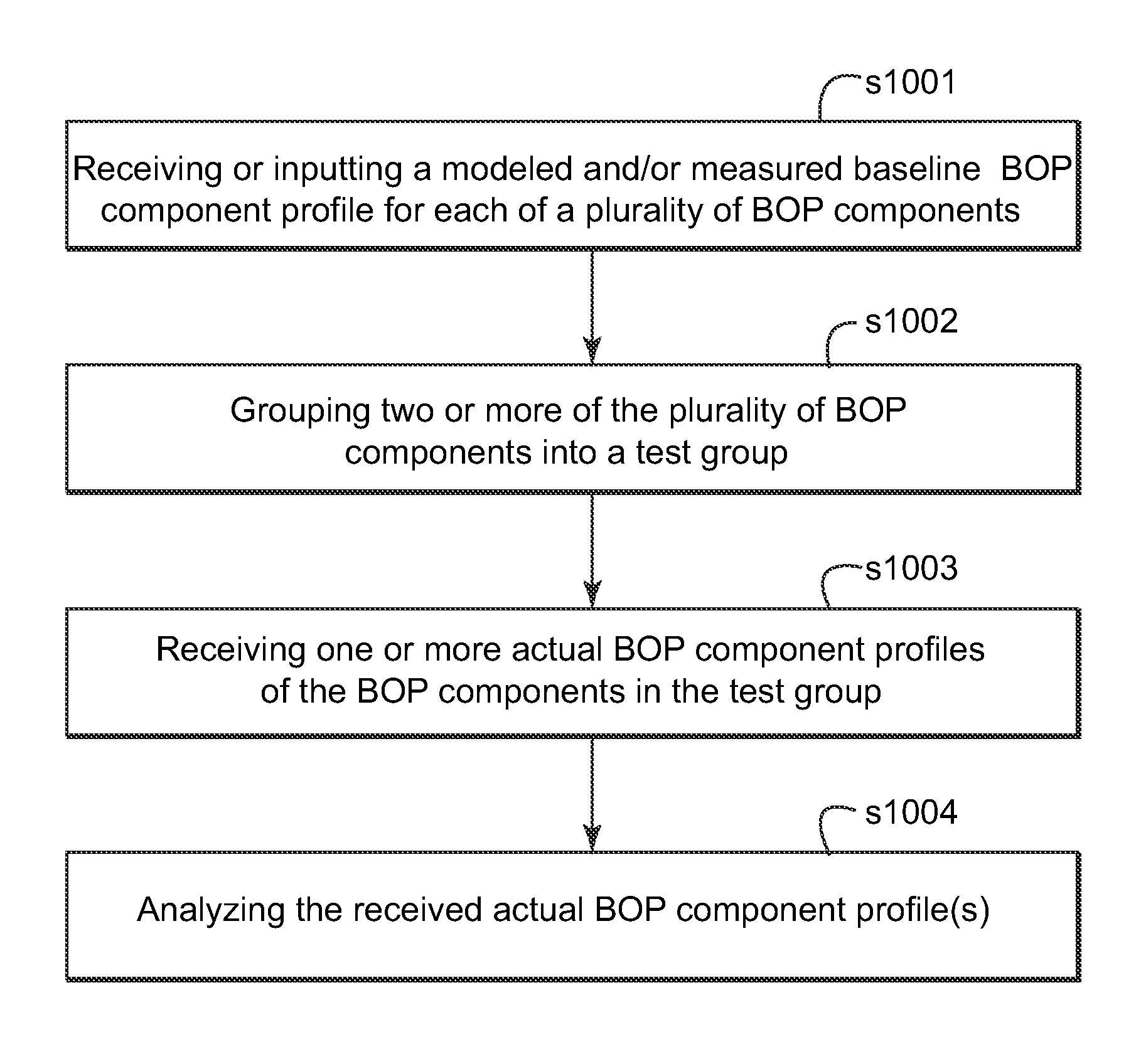
A system, device and method of monitoring components of a BOP of a subsea well. The method includes grouping, by the control device, two or more of a plurality of BOP components into a test group; receiving, by the control device, one or more actual BOP component profiles from the grouped BOP components in the test group; and analyzing, by the control device, the received one or more actual BOP component profiles. The two or more BOP components may be solenoid valves, flow meters, transducers, other devices, or a combination therein. The method includes grouping, by the control device, two or more of a plurality of BOP components into a test group; receiving, by the control device, one or more actual BOP component profiles from the grouped BOP components in the test group; and analyzing, by the control device software for the testing Pods, the received one or more actual BOP component profiles.

Description

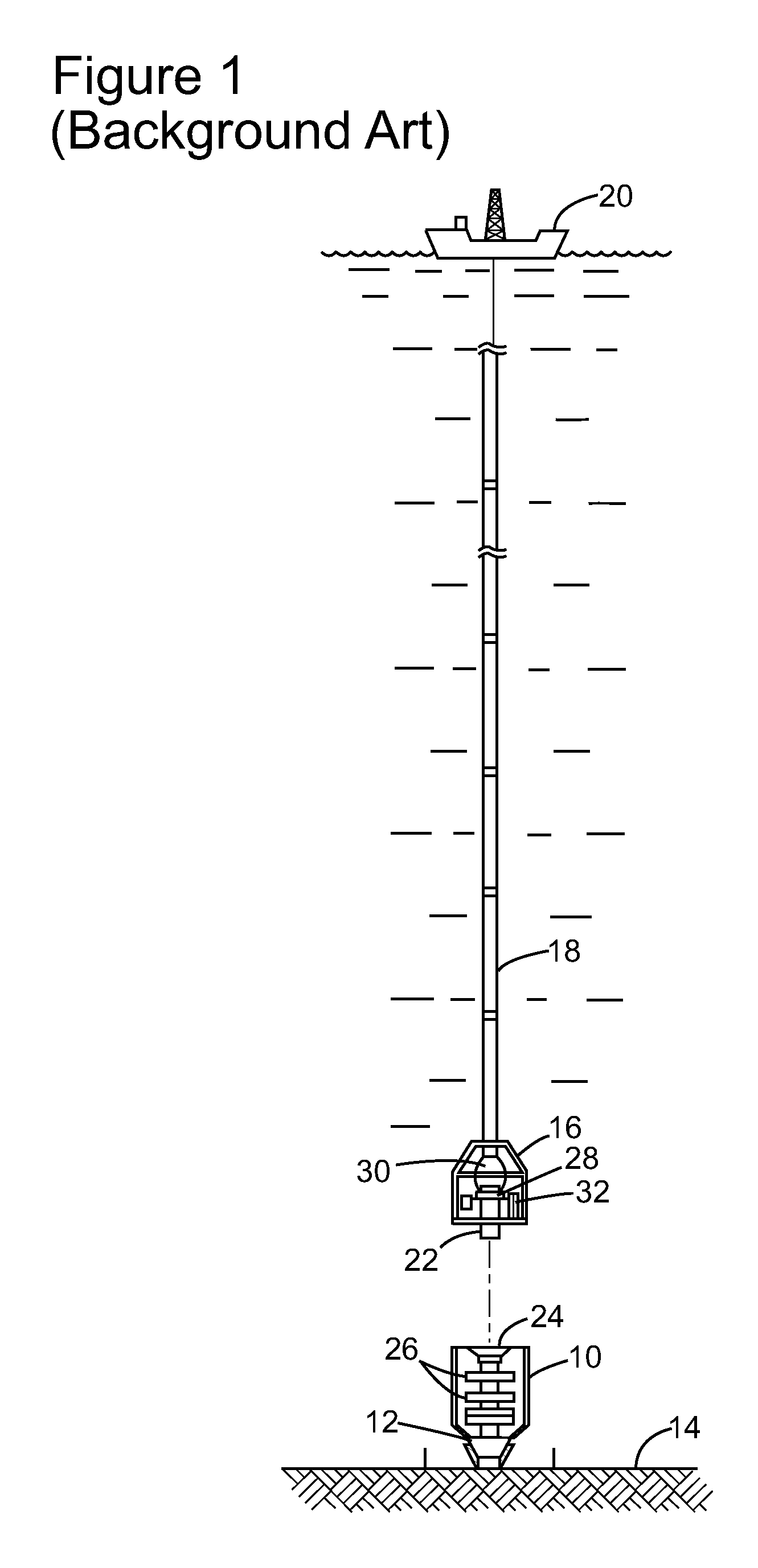
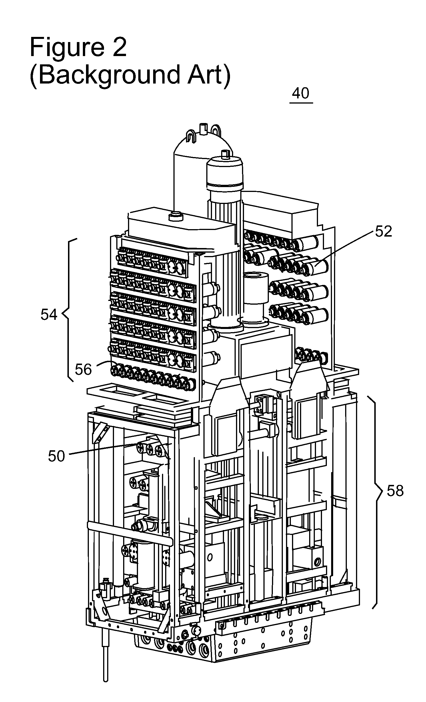
BACKGROUND[0001]1. Technical Field[0002]Embodiments of the subject matter disclosed herein generally relate to methods and systems and, more particularly, to mechanisms and techniques for monitoring a component of a subsea control module.[0003]2. Discussion of the Background[0004]Subsea oil and gas exploration becomes more challenging as the exploration depth increases. Complex devices are disposed on the ocean floor for extracting the oil and for the safety of the oil equipment and the environment. These devices have to withstand, among other things, high pressures (from 3,000 to 60,000 psi (200 to 4000 bar) or more) and highly corrosive conditions. Although precautions are taken when building these devices, component parts of these devices wear out with time and need to be replaced.[0005]As these parts are disposed on the ocean floor (sometimes more than 2000 m below sea level) and sometimes are provided inside larger components, access to them may be problematic. For example, FIG...

Claims


Application Information

Patent Timeline
Patent Type & Authority Applications(United States)
IPC IPC(8): G05D16/20E21B34/04
CPCE21B33/06E21B33/0355G01D21/00E21B33/064
Inventor EBENEZER, JOSEPH PREM
Owner HYDRIL USA MANUFACTURING LLC
Learn More