Substrate cleaning method and substrate cleaning device

a cleaning method and substrate technology, applied in the direction of cleaning process and equipment, cleaning using liquids, lighting and heating equipment, etc., to achieve the effect of preventing a large amount of reaction products, preventing a reduction in collection efficiency, and promoting the formation of clusters

Active Publication Date: 2013-03-07
TOKYO ELECTRON LTD +1
View PDF4 Cites 10 Cited by
  • Summary
  • Abstract
  • Description
  • Claims
  • Application Information

AI Technical Summary

Benefits of technology

[0036]In accordance with the present invention, since the pressure when the cleaning gas is sprayed ranges from 0.3 MPa to 2.0 MPa, when the gas is sprayed, it causes a rapid adiabatic expansion in the low pressure atmosphere so that the gas molecules are cooled rapidly. As a result, it is possible to promote the formation of the cluster.
[0037]In accordance with the present invention, since the gas spraying unit moves along the surface of the substrate while spraying the high pressure gas, it is possible to remove the foreign material from the entire surface of the substrate.
[0038]In accordance with the present invention, another cluster including CO2 blast or gas molecules is ejected toward the cooling unit, and the foreign material captured by the cooling unit is detached from the cooling unit. Accordingly, it is possible to prevent a large amount of the reaction product from being attached to the cooling unit, thereby preventing a reduction in efficiency of collection of the foreign material removed from the substrate by the cooling unit.
[0039]In accordance with the present invention, since the gas spraying unit sprays the gas from the hole having a diameter of 0.02 mm to 1.0 mm, it is possible to increase an expansion rate of the gas when it is sprayed, and it is possible to further promote the formation of the cluster.
[0040]In accordance with the present invention, since the high pressure gas is sprayed to the substrate in the multiple directions, it is possible to prevent the collision of the cluster from failing to occur in some places in the substrate.
[0041]In accordance with the present invention, the pressure of the high pressure gas being sprayed in each of the multiple directions is set differently, and / or a spraying timing of the high pressure gas is set differently. Accordingly, it is possible to allow the high pressure gas to pulsate, thereby largely improving the cleaning ability of the high pressure gas.

Problems solved by technology

Since the foreign materials or the like on the wafer adversely affects the processing of the next step, it is necessary to remove it as much as possible.

Method used


Image

  • Substrate cleaning method and substrate cleaning device
  • Substrate cleaning method and substrate cleaning device
  • Substrate cleaning method and substrate cleaning device

Examples


Embodiment Construction

[0046]Hereinafter, an embodiment of the present invention will be described in detail with reference to the accompanying drawings.

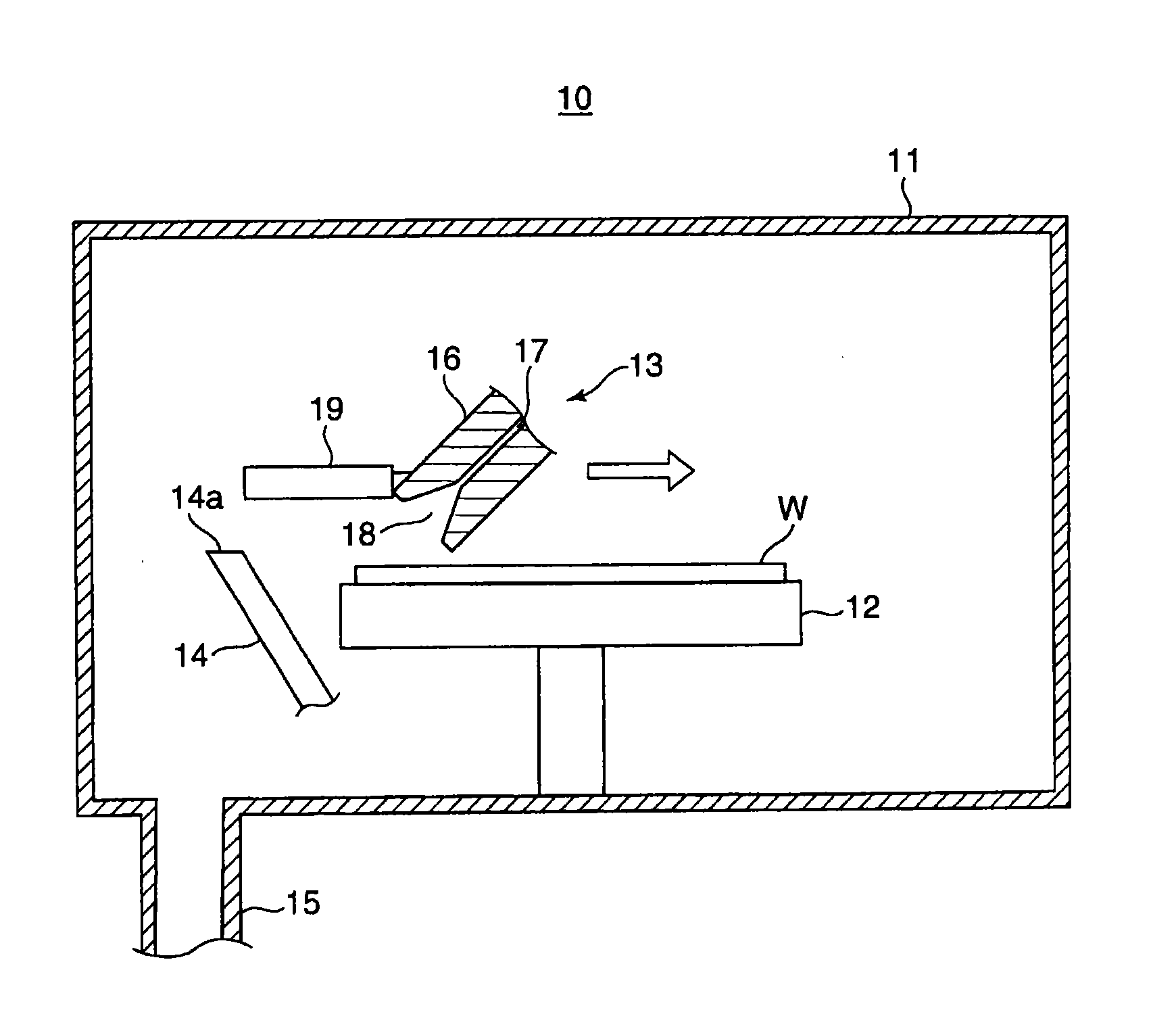
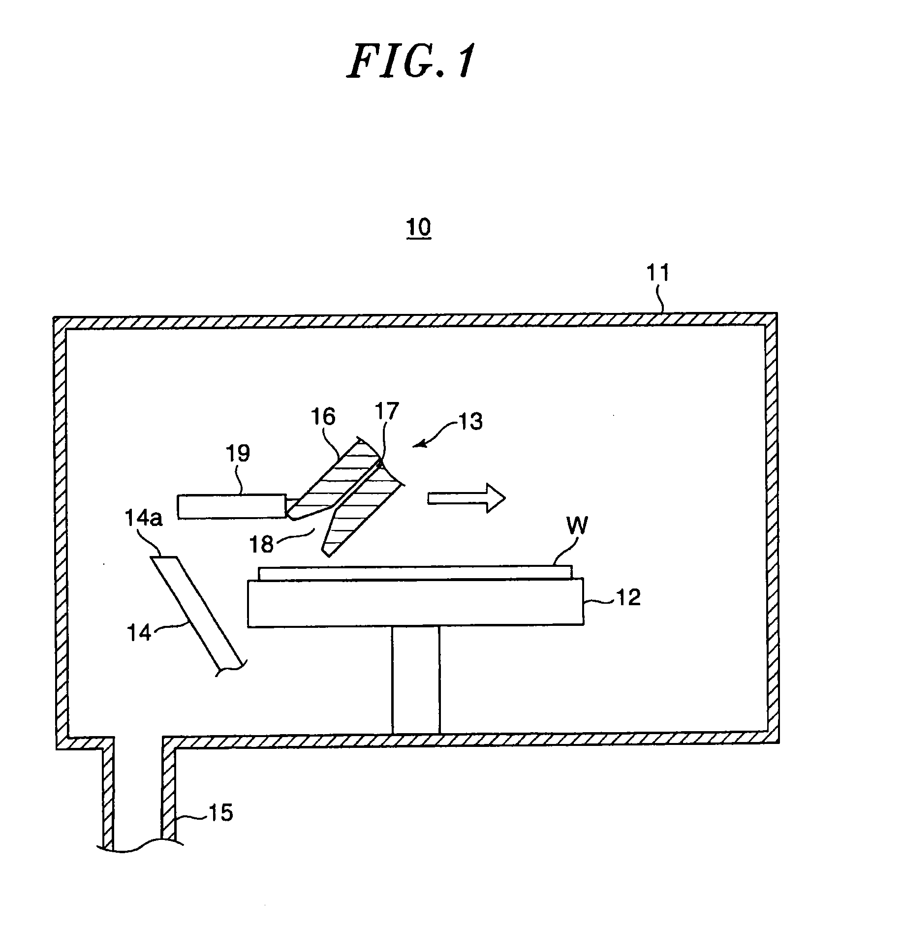
[0047]FIG. 1 is a cross-sectional view schematically showing a configuration of a substrate cleaning device for performing a substrate cleaning method according to an embodiment of the present invention.

[0048]In FIG. 1, a substrate cleaning device 10 includes a chamber 11 (processing chamber) whose inner atmosphere is decompressed to nearly a vacuum level, e.g., 1 Pa and which accommodates a semiconductor wafer (hereinafter, simply referred to as “wafer”) serving as a substrate, a mounting table 12 which has a table shape and is disposed in the chamber 11 to mount the wafer, a gas spraying nozzle 13 (gas spraying unit) which is disposed in the chamber 11 to face the wafer mounted on the mounting table 12, a cleaning nozzle 14 (ejection unit) which is disposed in the vicinity of the mounting table12, and an exhaust pipe 15 which exhausts a gas in the chamb...


PUM


Abstract

A substrate cleaning method includes removing a foreign material attached to a substrate while preventing deterioration of the substrate and any film formed on or above the substrate. A cleaning gas at a pressure between 0.3 MPa and 2.0 MPa is sprayed towards a wafer W with attached foreign material 22 placed in a near-vacuum, producing clusters 21 made up of a multitude of gas molecules 20, and the clusters 21 collide with the wafer W without undergoing ionization.

Description

FIELD OF THE INVENTION[0001]The present invention relates to a substrate cleaning method and a substrate cleaning device, and more particularly to a substrate cleaning method and a substrate cleaning device for cleaning a substrate without the use of liquid.BACKGROUND OF THE INVENTION[0002]In case of manufacturing electronic devices on a substrate, e.g., a wafer through a plurality of steps, a desired pattern including, e.g., trenches or holes is formed on the wafer by performing a film formation process or etching process on the wafer in each step. At this time, a reaction product or unintended foreign substance may be generated in the film formation process or etching process and attached onto the wafer. Since the foreign materials or the like on the wafer adversely affects the processing of the next step, it is necessary to remove it as much as possible.[0003]Conventionally, as a method of removing a foreign material on the wafer, a method of washing the foreign material by immer...

Claims


Application Information

Patent Timeline
Patent Type & Authority Applications(United States)
IPC IPC(8): B08B5/02
CPCH01L21/02057B08B5/02H01L21/02046H01L21/67028H01L21/302
Inventor MATSUI, HIDEFUMIMORIYA, TSUYOSHINARUSHIMA, MASAKI
Owner TOKYO ELECTRON LTD
Why Eureka
Try Eureka