Terminal for an electrical switchgear

a technology for terminals and switchgears, applied in the direction of switches, earthing arrangements, contacts, etc., to achieve the effect of reducing the diameter of the cavity defined by the inner wall, reducing the diameter of the cavity, and reducing the diameter of the terminal

Active Publication Date: 2013-03-07
EATON INTELLIGENT POWER LIMITED
View PDF4 Cites 5 Cited by
  • Summary
  • Abstract
  • Description
  • Claims
  • Application Information

AI Technical Summary

Benefits of technology

[0007]According to the invention, there is provided a terminal for an electrical switch gear according to claim 1. Locating a terminal contact in a recess formed in the inner wall of the housing, wherein the terminal contact is flush with the inner surface, means that the diameter of the cavity defined by inner wall can be reduced optimally because it does not need to accommodate the terminal contact. Advantageously, reducing the diameter of the cavity means that the diameter of the terminal can likewise be reduced (over much of the circumference of terminal, if not all of it) which provides for a more compact terminal.

Problems solved by technology

In fixed switchgear the main circuit breaker is fastened within the installation by fasteners, for example bolts, and cannot be removed from the installation without using tools to undo the fasteners.

Method used


Image

  • Terminal for an electrical switchgear
  • Terminal for an electrical switchgear
  • Terminal for an electrical switchgear

Examples


Embodiment Construction

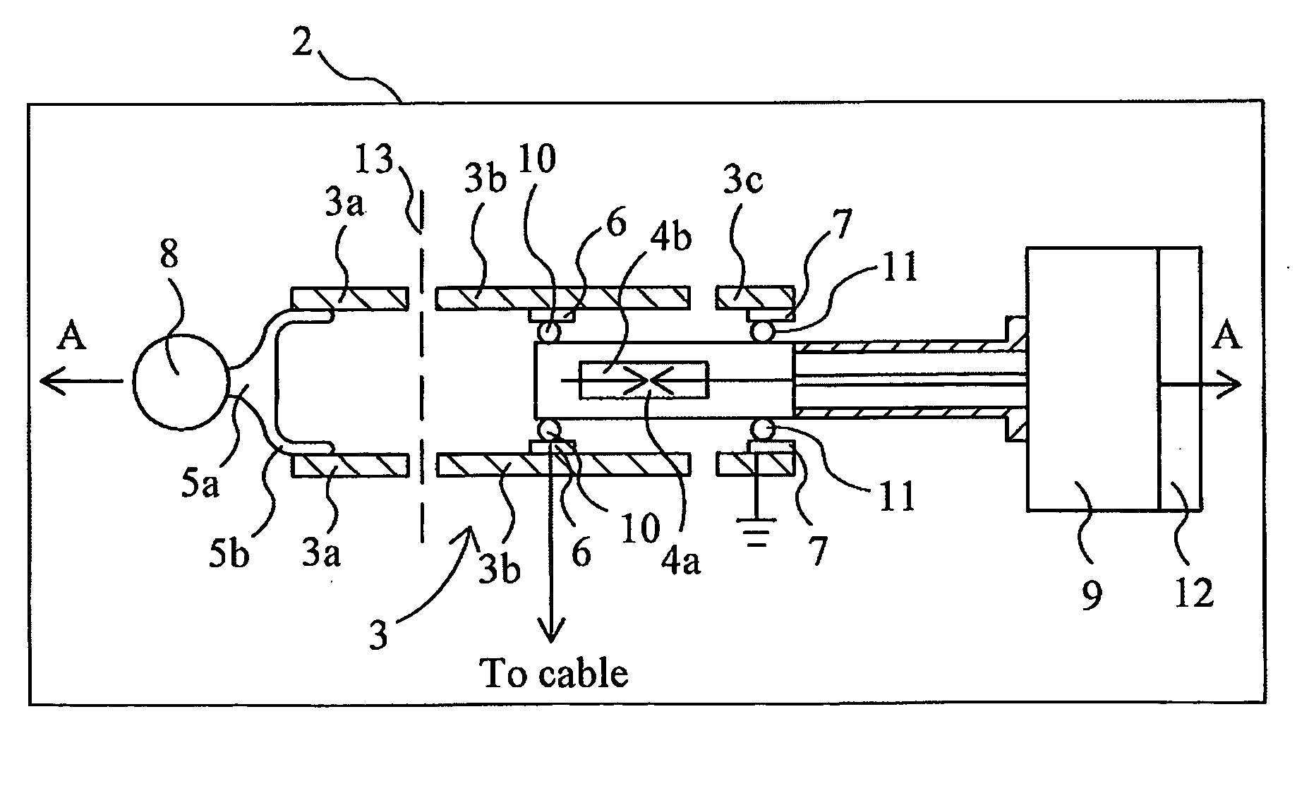
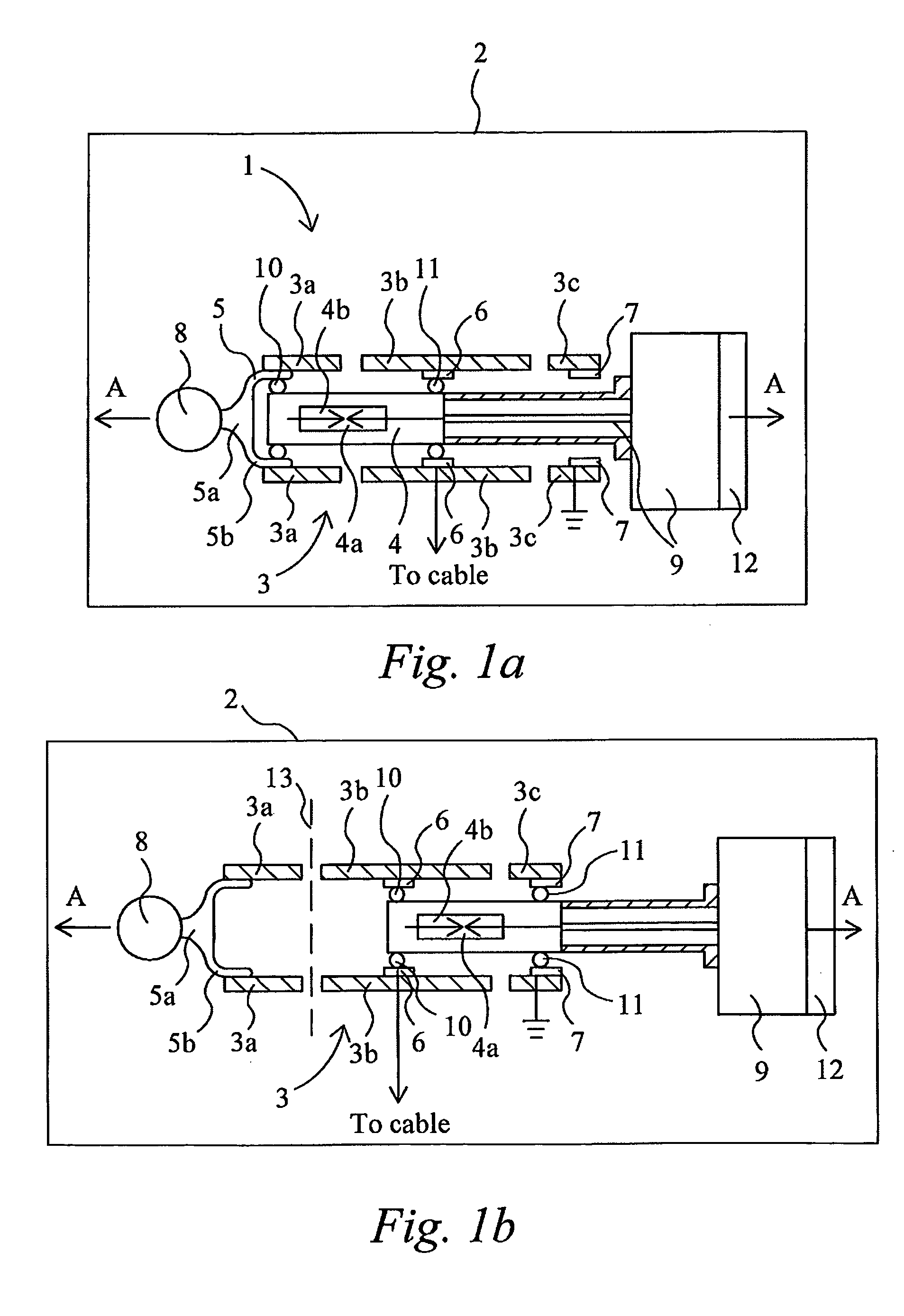
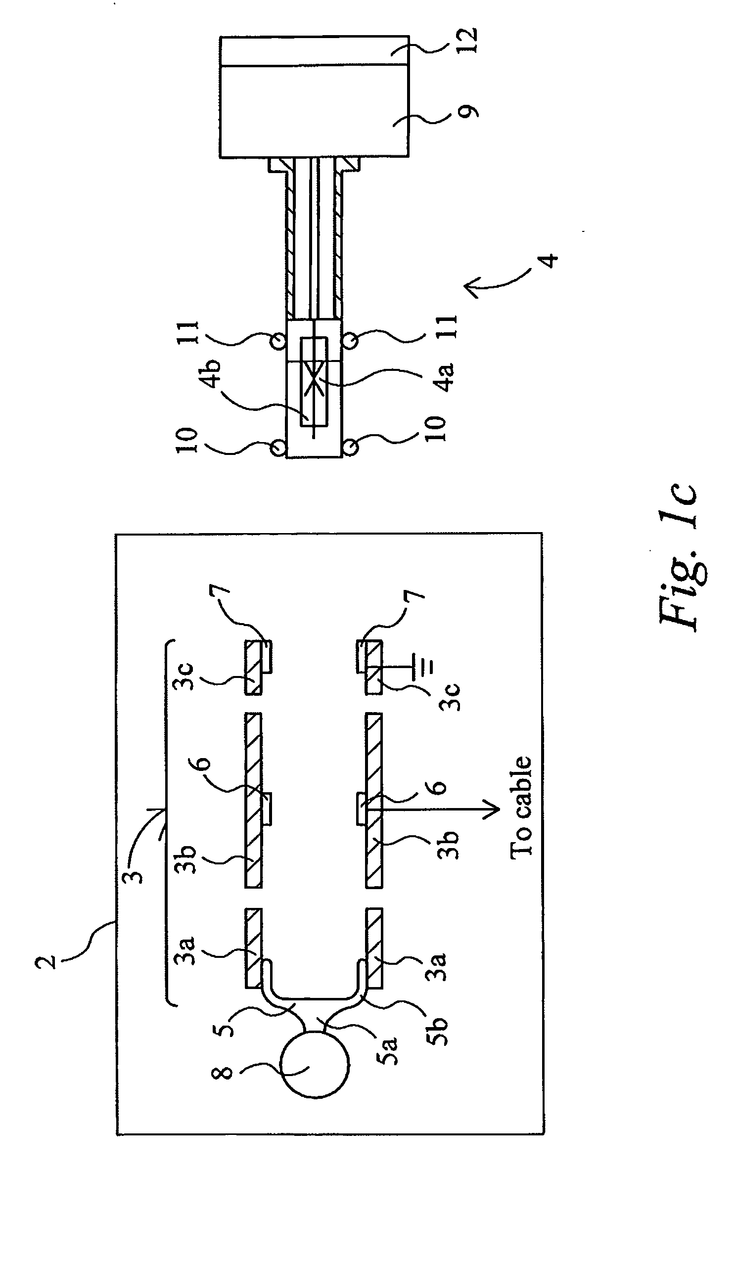
[0022]Referring to FIGS. 1a to 1c, a switch arrangement 1 for an electrical switchgear 2 comprises an electrical pole or terminal 3 and a circuit breaker 4. The terminal 3, is fixed within the switchgear 2 and comprises a housing made up of first 3a, second 3b and third 3c electrically insulating tubular sections of substantially equal diameter, which as will be explained in greater detail below have a substantially oval cross section, and which are spaced apart lengthwise along a common axis A. The three tubular sections may for example be formed of an epoxy resin material. Each of the three tubular sections 3a, 3b and 3c has a respective electrical contact 5, 6, 7 located inside of it. The first section 3a has a bus bar contact 5 for making an electrical connection to an electrical bus 8 of the switchgear 2, the second section 3b has a cable contact 6 for making an electrical connection to a cable (not shown) of the switch gear 2 and onwards to a load (not shown) and the third sec...


PUM


Abstract

A terminal for an electrical switchgear, the terminal comprises a housing arrangement (3) comprising an electrically insulating material and having an inner surface defining a cavity; and a first terminal electrical contact (61) contained in the housing arrangement for making an electrical connection with an electrical component (41) insertable into the cavity The first terminal electrical contact is located in a first recess (40) formed in the inner surface and is flush with the inner surface of the housing arrangement.

Description

FIELD OF THE INVENTION[0001]The present invention relates to a terminal for an electrical switchgear.BACKGROUND[0002]As is well known, a switchgear is an integrated assembly of switches, buses fuses and other components used to isolate electrical equipment at an electrical installation, for example, an electrical power sub-station. Switchgear is used to both de-energise equipment to allow work to be done and to clear faults downstream of the switchgear. Switchgear is often housed in a metal cabinet at the installation.[0003]In known installations, a distinction is made between so called ‘fixed switchgear’ and so called ‘withdrawable switchgear’. In fixed switchgear the main circuit breaker is fastened within the installation by fasteners, for example bolts, and cannot be removed from the installation without using tools to undo the fasteners. In withdrawable switchgear additional constructional features enable the main circuit breaker to be withdrawn from the installation (and put b...

Claims


Application Information

Patent Timeline
Patent Type & Authority Applications(United States)
IPC IPC(8): H02B11/02H01H1/58H01H15/02
CPCH01H1/365H01H1/40H02B11/28H02B11/04H01H33/662
Inventor BINNENDIJK, MARTENLAMMERS, AREND
Owner EATON INTELLIGENT POWER LIMITED
Why Eureka
Try Eureka