Method for mixing airflows in a turbofan and engine outlet for operation

Active Publication Date: 2013-03-07
SN DETUDE & DE CONSTR DE MOTEURS DAVIATION S N E C M A
View PDF4 Cites 5 Cited by
  • Summary
  • Abstract
  • Description
  • Claims
  • Application Information

AI Technical Summary

Benefits of technology

[0013]The invention aims at providing a sufficient air exchange in the engine area with a static pressure in the outlet area of the air exchange duct so sma

Problems solved by technology

But the obstruction created by the presence of the mixer M1 leads to areas with high local increase of the static pressure upstream to

Method used


Image

  • Method for mixing airflows in a turbofan and engine outlet for operation
  • Method for mixing airflows in a turbofan and engine outlet for operation
  • Method for mixing airflows in a turbofan and engine outlet for operation

Examples


Embodiment Construction

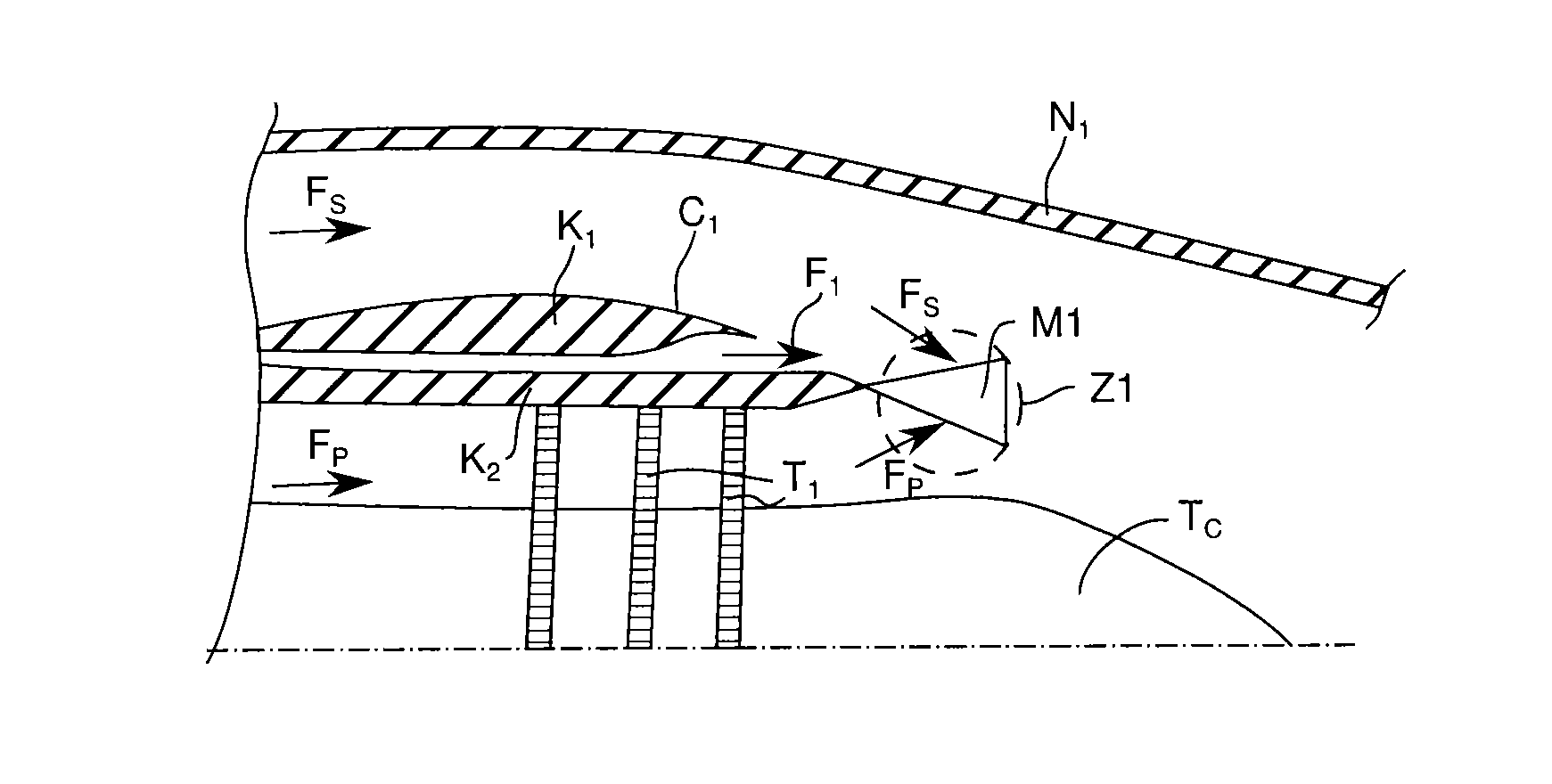
[0027]Herein, the term “axial” means parallel to the longitudinal axis of a turbojet engine, the term “radial” defining itself with respect to this longitudinal axis. The terms “upstream” and “downstream” relate to the global direction of the air flows along the longitudinal axis of a turbofan, from the entrance to an air boot of air blower to their final exhaust in the nozzle. In the figures, the various longitudinal lines which appear on the lobes allow to suggest the curvatures of these lobes by the density of closure and their own curvature. Besides, the terms “hot lobes” and “cold lobes” indicate the lobes which guide respectively the hot primary airflow and the cold secondary airflow.

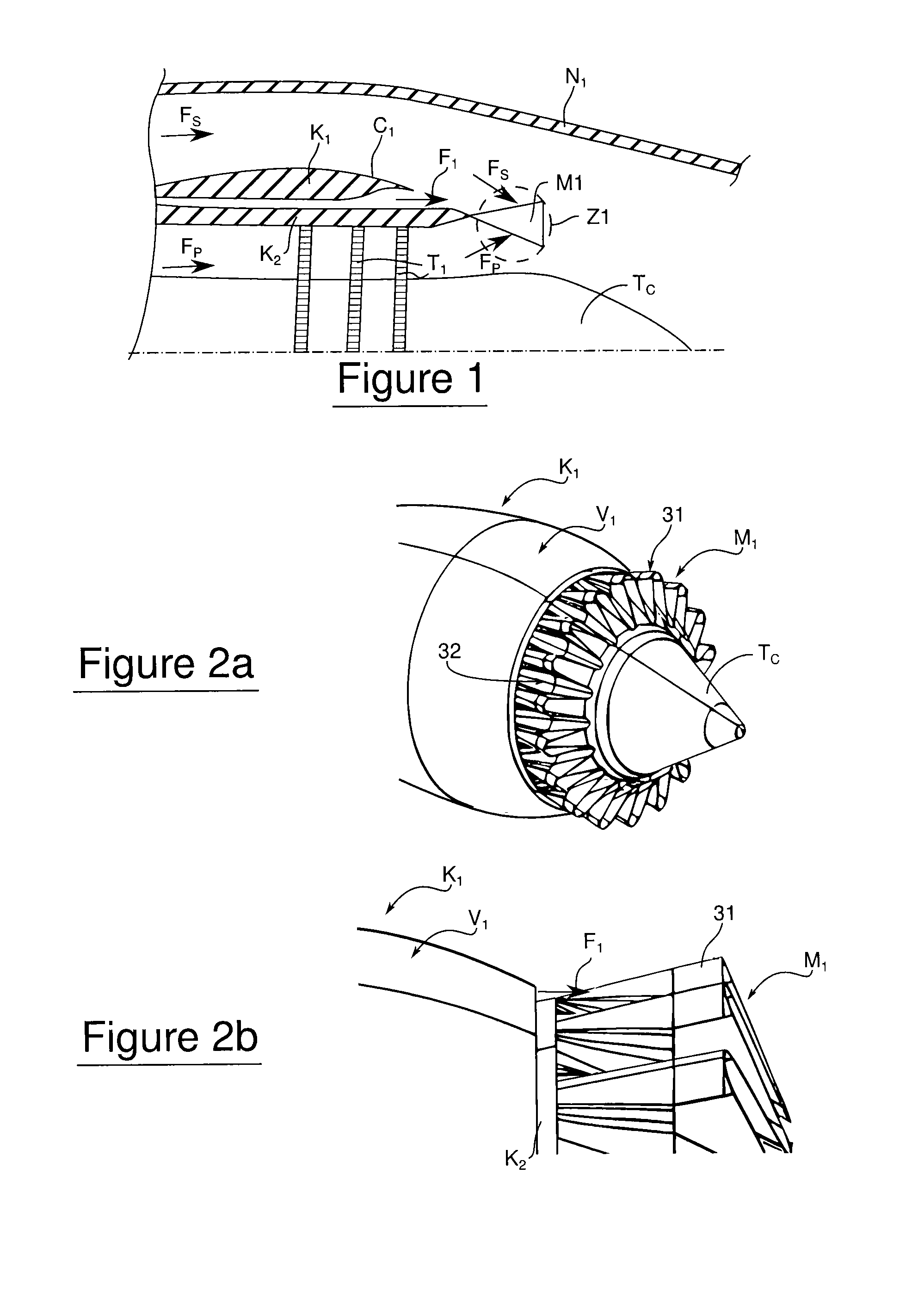
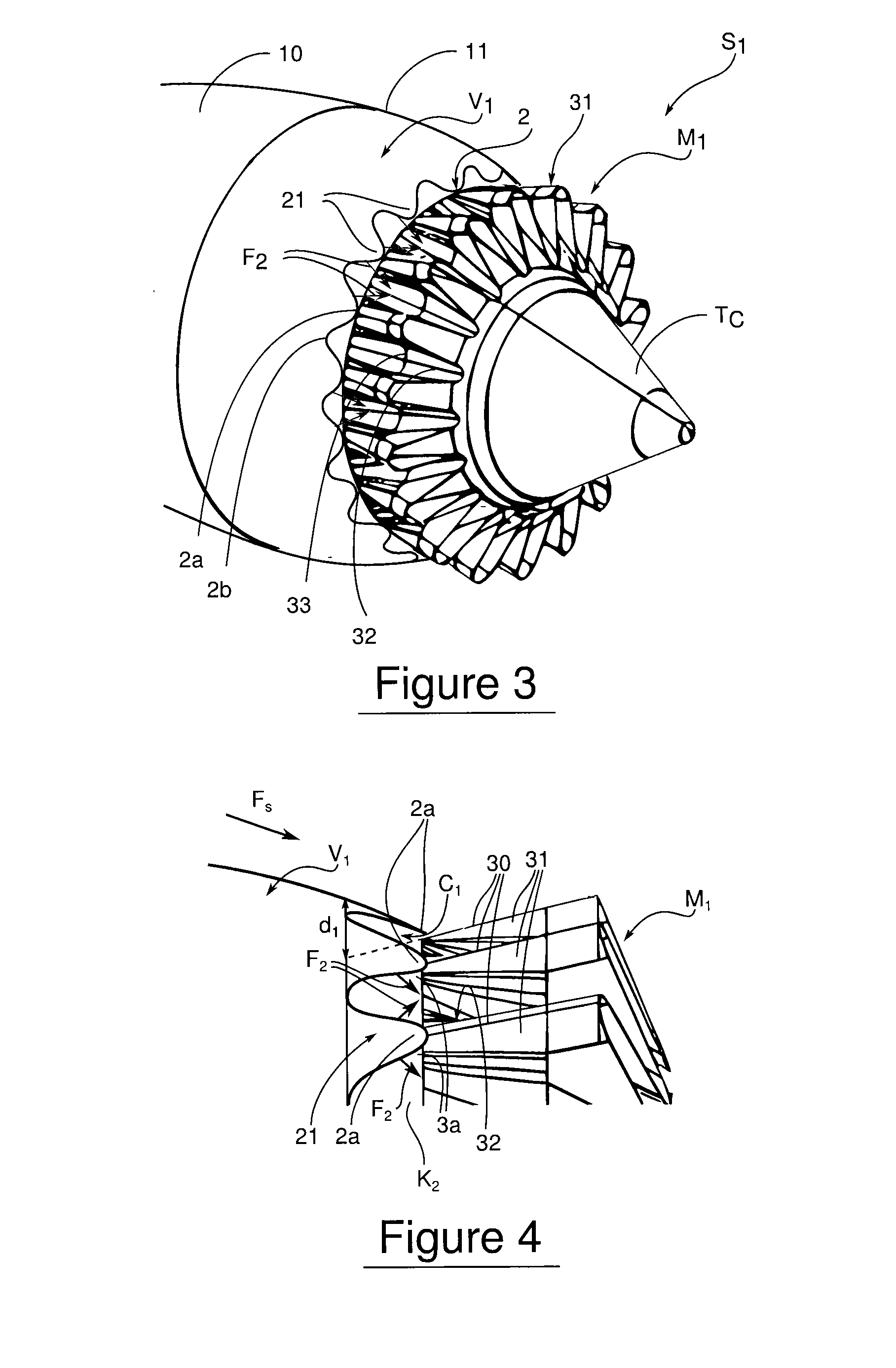
[0028]Referring to perspective and front (partial) views of a back end of turbojet engine, in the FIGS. 3 and 4, equipped with a nozzle cone Tc, a mixer M1 with lobes is adapted on the internal fairing K2 of the turbines (not visible) of this turbojet engine. At the trailing edge of the end ferrul...


PUM


Abstract

The invention aims at providing a sufficient air exchange in the engine area without raising the static pressure in the outlet area of the air exchange duct. In order to do this, the invention provides for an outlet section capable of concentrating the outlet of the exchange airflow towards zones with smaller static pressure.
An turbojet engine outlet according to the invention provides an engine cowl, which comprises an external wall of a circumferential duct in which circulates an exchange airflow of the turbines, and an airflow mixer. At the outlet, the duct delivers the exchange airflow towards the mixer for the primary and secondary airflows of the turbojet engine. The mixer presents hot and cold lobes. In particular, the engine outlet also comprises guiding means of the exchange airflow towards the cold lobes.

Description

TECHNICAL FIELD[0001]The invention relates to a method for mixing primary and secondary airflows in an aircraft turbojet engine, as well as to an engine output capable of implementing such a method.[0002]In turbojet engines with mixed double airflow, the air exchange of the engines allows to optimize their operation in the entire domain of flight: takeoff, cruise, search, landing, whatever is the by-pass ratio between the primary and secondary airflows.[0003]Turbofans (turbojet engines with double airflow) are generally equipped with an air blower which provides the major part (for example, 80%) of the thrust. They comprise, from upstream to downstream with respect to the air flow, the air blower, compressors stages, one or more combustion chambers, expansion turbines stages and two jet nozzles: nozzle for hot primary airflow, which comes from combustion, and nozzle for cold secondary airflow, which comes from the air blower outwardly concentric with the primary airflow.[0004]More p...

Claims


Application Information

Patent Timeline
IPC IPC(8): F02K1/46F02K1/38
CPCF02K1/34F02K1/386F05D2260/96F02K3/077F02K1/48B64D33/06F02K1/46F05D2250/184
Inventor MOUCHOUX, PIERRICKDE VULPILLIERES, ERICMABBOUX, GAÉTAN JEANVERDIER, MARION
Owner SN DETUDE & DE CONSTR DE MOTEURS DAVIATION S N E C M A
Why Eureka
Try Eureka