
Joint apparatus, joint system, and joint method

a joint apparatus and joint technology, applied in the directions of packaging, transportation and packaging, labelling, etc., can solve the problems of warpage or distortion of the wafer, the thickness of the wafer after polishing processing does not become uniform within the wafer, and the wafer becomes partially thick or thin, so as to suppress the occurrence of warpage or distortion in the wafer

Inactive Publication Date: 2013-03-14
TOKYO ELECTRON LTD
View PDF8 Cites 11 Cited by
  • Summary
  • Abstract
  • Description
  • Claims
  • Application Information

AI Technical Summary

Benefits of technology

The invention is a joint apparatus that prevents warping or distortion in a wafer after it is joined with another substrate. This is accomplished by cooling the wafer to a temperature that does not cause warping or distortion before transferring it outside the processing container. By doing so, the joint apparatus can suppress the occurrence of warping or distortion in the processing target substrate.

Problems solved by technology

However, the thickness of the wafer after the polishing processing does not become uniform within the wafer but the wafer becomes partially thick or thin in some cases.
From earnest study by the present inventors about this point, it is is found that warpage or distortion occurs in the wafer at the stage before the polishing processing, and the polishing processing performed in this state causes variations in thickness of the wafer after the polishing.
Therefore, a portion of the wafer after joining which is not held by the wafer transfer apparatus is warped or distorted.

Method used


Image

  • Joint apparatus, joint system, and joint method
  • Joint apparatus, joint system, and joint method
  • Joint apparatus, joint system, and joint method

Examples


Embodiment Construction

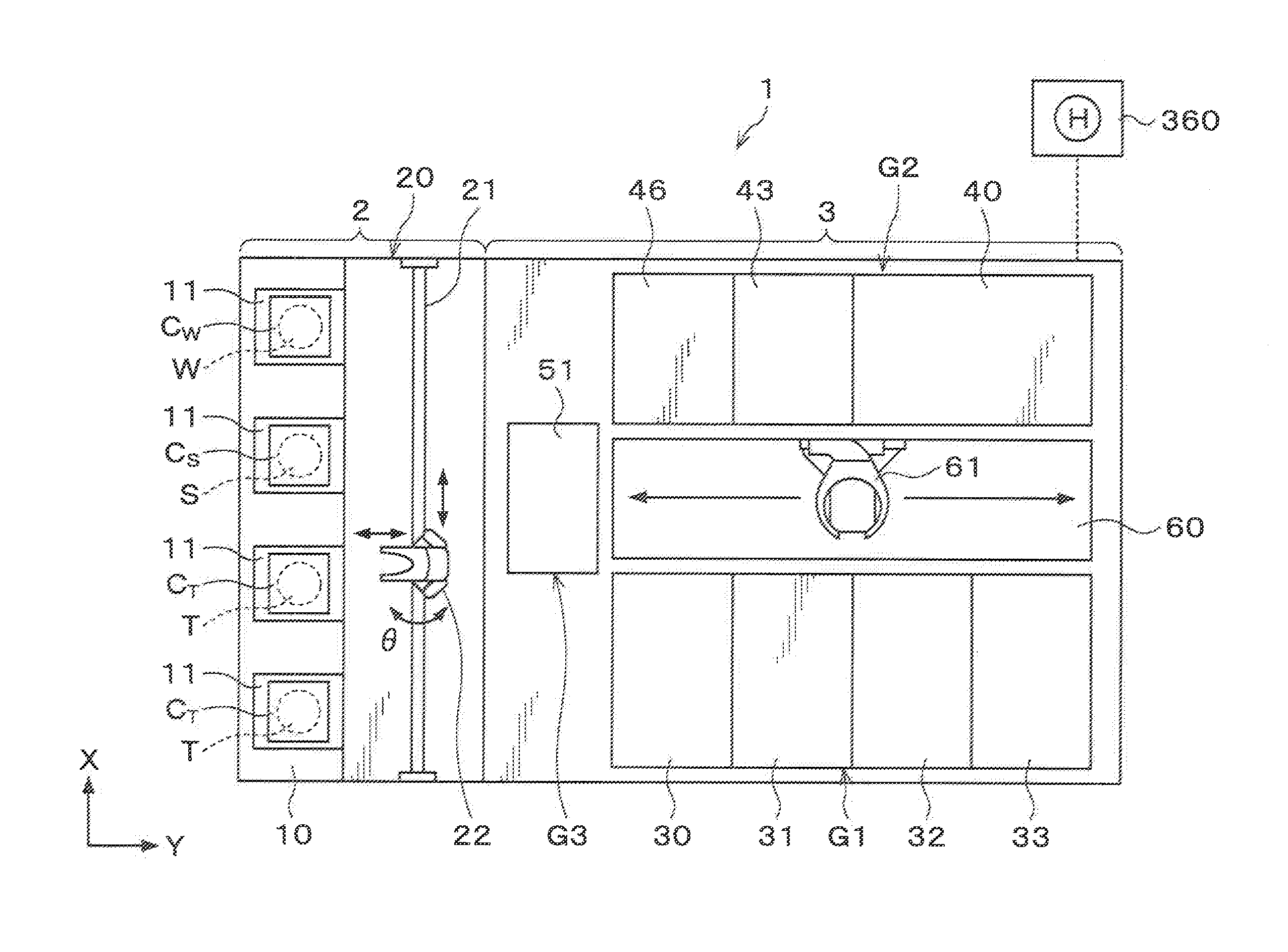
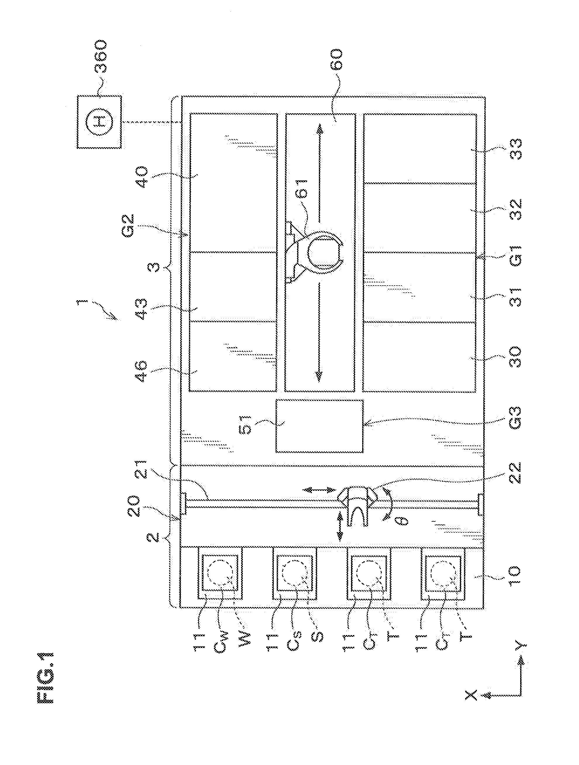
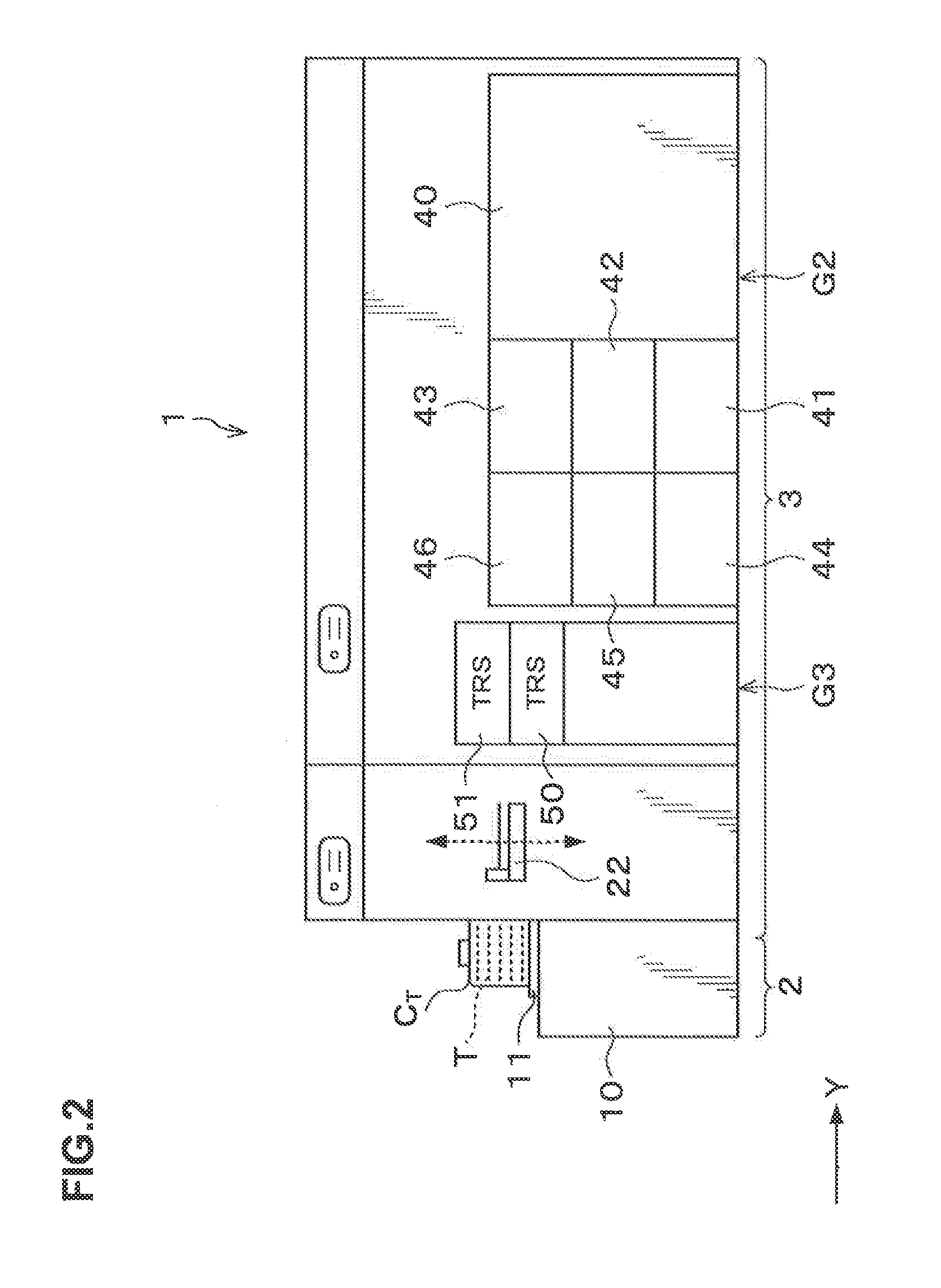
[0048]Hereinafter, embodiments of the present invention will be described. FIG. 1 is a plan view illustrating the outline of a configuration of a joint system 1 including a joint apparatus according to this embodiment. FIG. 2 is a side view illustrating the outline of the internal configuration of the joint system 1,

[0049]In the joint system 1, for example, a processing target wafer W as a processing target substrate and a supporting wafer S as a supporting substrate are joined together, for example, via an adhesive G as illustrated in FIG. 3. Hereinafter, in the processing target wafer W, the surface to be joined with the supporting wafer S via the adhesive G is referred to as a “joint surface WJ” as a front surface and the surface opposite to the joint surface WJ is referred to as a “non-joint surface WN” as a rear surface. Similarly, in the supporting wafer S, the surface to be joined with the processing target wafer W via the adhesive G is referred to as a “joint surface SJ” as ...


PUM

PropertyMeasurementUnit
temperatureaaaaaaaaaa
pressureaaaaaaaaaa

Abstract

A joint apparatus that joins a processing target substrate and a supporting substrate together, includes: a processing container that is capable of hermetically closing an inside thereof; a joint unit that joins the processing target substrate and the supporting substrate together by pressing the processing target substrate and the supporting substrate via an adhesive; and a superposed substrate temperature regulation unit that temperature-regulates a superposed substrate joined in the joint unit, wherein the joint unit and the superposed substrate temperature regulation unit are arranged in the processing container, A delivery unit for delivering the processing target substrate, the supporting substrate, or the superposed substrate to / from an outside of the processing container is provided in the processing container, and the superposed substrate temperature regulation unit is provided in the delivery unit.

Description

BACKGROUND OF THE INVENTION[0001]1. Field of the Invention[0002]The present invention relates to a joint apparatus that joins a processing target substrate and a supporting substrate together, a joint system. includes the joint apparatus, and a joint method using the joint apparatus.[0003]2. Description of the Related Art[0004]In recent years, for example, in a manufacturing process of a semiconductor device, the diameter of a semiconductor wafer (hereinafter, referred to as a “wafer”) increasingly becomes larger. Further, the wafer is required to be thinner in a specific process such as packaging. For example, when a thin wafer with a large diameter is transferred or subjected to polishing processing as it is, warpage or break can occur in the wafer. Therefore, in order to reinforce the wafer, for example, bonding the wafer to a wafer being a supporting substrate or a glass substrate is performed.[0005]The bonding of the wafer and the supporting substrate is performed by intervenin...

Claims


Application Information

Patent Timeline
Patent Type & Authority Applications(United States)
IPC IPC(8): C09J5/06
CPCH01L21/67092H01L21/67109H01L21/68707H01L21/6838H01L21/67742H01L21/02H01L21/683
Inventor OKADA, SHINJISHIRAISHI, MASATOSHIDEGUCHI, MASATOSHIYOSHITAKA, NAOTOSUGIHARA, SHINTAROMATSUNAGA, MASATAKA
Owner TOKYO ELECTRON LTD
Learn More