Dielectric loaded fluids for high voltage switching

a high-voltage switching and loaded fluid technology, applied in the field of dielectric fluids, can solve the problems that the switching using oil dielectrics may still demonstrate erratic breakdown patterns

Inactive Publication Date: 2013-03-14
UNIVERSITY OF MISSOURI
View PDF1 Cites 15 Cited by
  • Summary
  • Abstract
  • Description
  • Claims
  • Application Information

AI Technical Summary

Benefits of technology

[0018]FIG. 7 is a graph depicting the effect of a single particle's distance ...

Problems solved by technology

During self-break operation, however, switches using oil dielectrics may still demonstrate erra...

Method used


Image

  • Dielectric loaded fluids for high voltage switching
  • Dielectric loaded fluids for high voltage switching
  • Dielectric loaded fluids for high voltage switching

Examples


Embodiment Construction

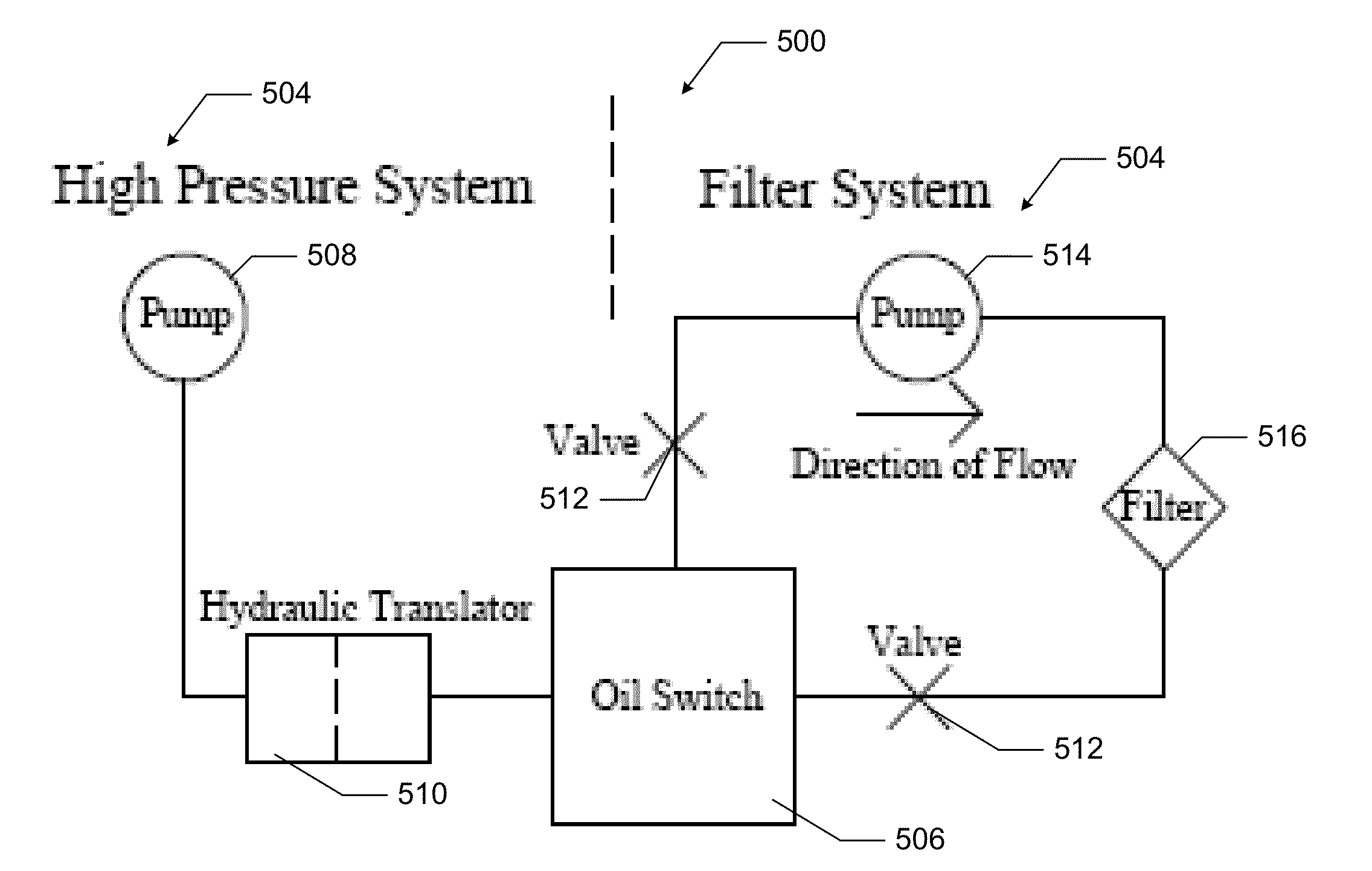
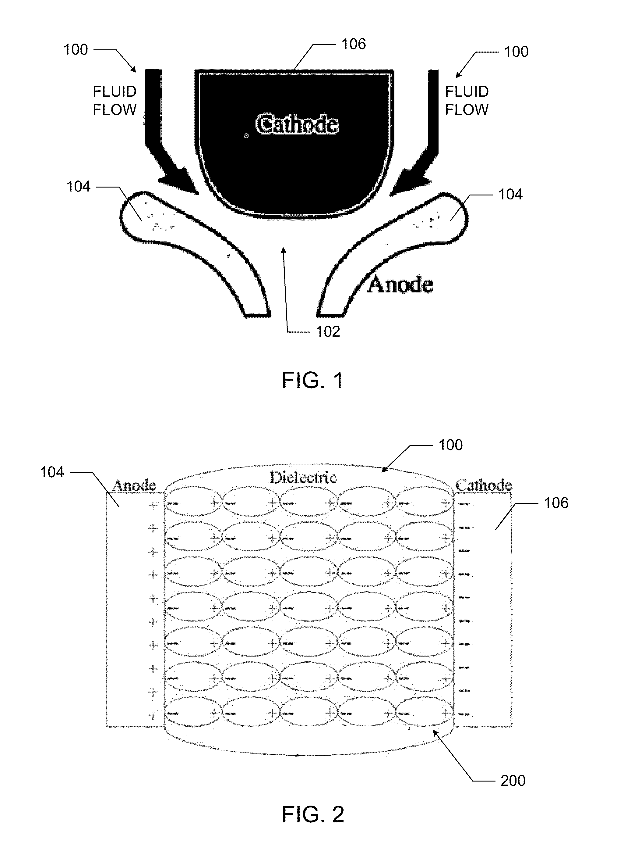
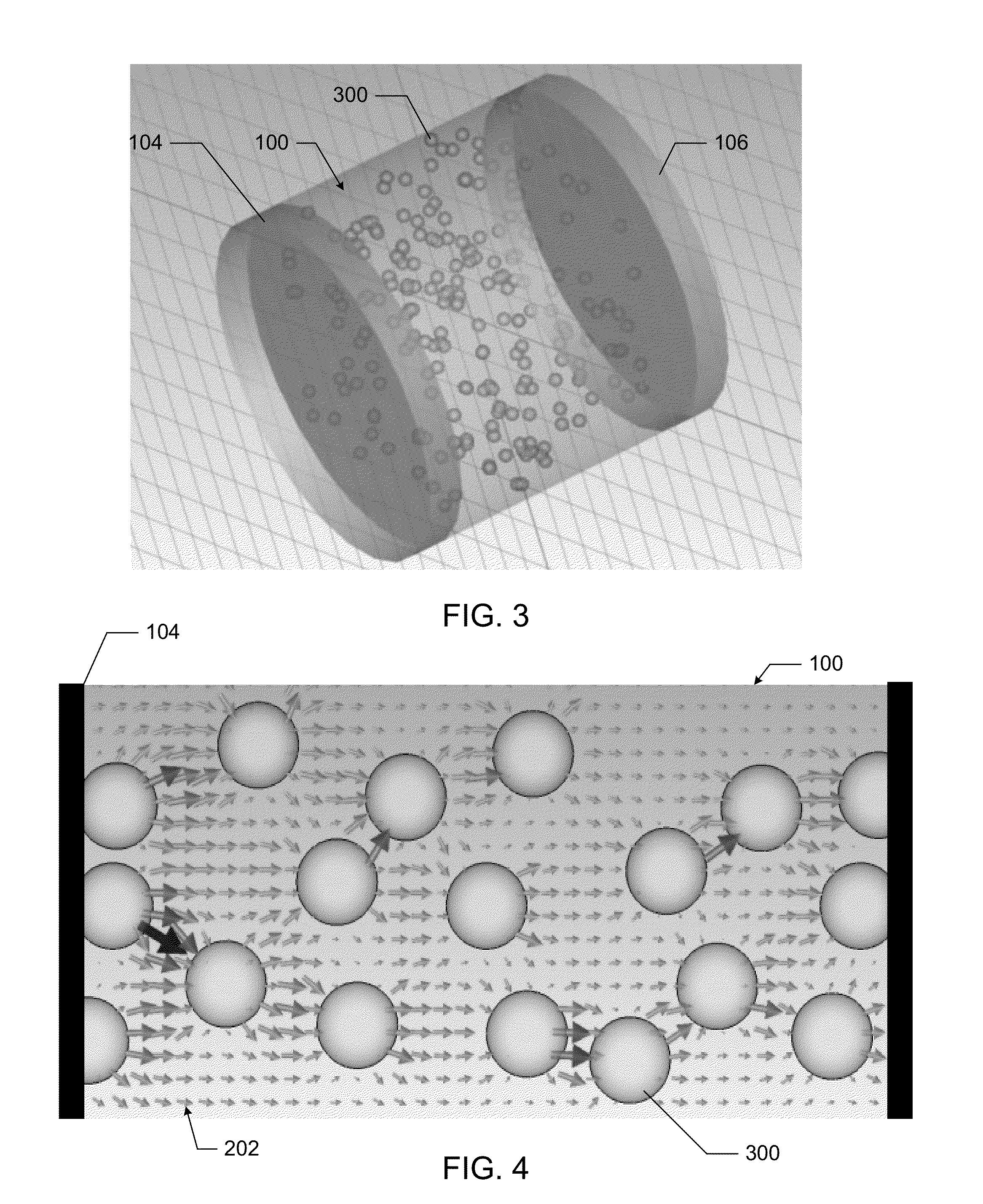
[0022]The present disclosure relates to a dielectric fluid that reduces the voltage breakdown jitter in high voltage switches and spark gaps. In various embodiments, the dielectric fluid can be used in flowing or pressurized nonflowing spark gaps. In one aspect, the pressurized fluid reduces the size of the vapor bubble resulting from the arc in the liquid. An isostatic pressure is applied reducing the size of the vapor bubble. The isostatic pressure also increases the voltage breakdown jitter of the switch. The pressure inherently reduces microbubbles that result from the formation of electrons emitted from the cathode surface. Typically, the emitted electrons result from high electrical field levels at the surface of the cathode that are caused by electrode pitting and the electrode gap spacing.

[0023]In a high pressure spark gap, a minimum of 2 electrodes are utilized for the switch. By way of example, and not limitation, exemplary high voltage switches are disclosed in U.S. Pat. ...


PUM


Abstract

This disclosure relates to methods and systems to reduce high voltage breakdown jitters in liquid dielectric switches. In particular, dielectric liquids have been produced that contain a suspension of nanoparticles and a surfactant to reduce the breakdown jitter. In one embodiment, the suspended nanoparticles are Barium Strontium Titanate (BST) nanoparticles.

Description

FIELD OF THE INVENTION[0001]The invention generally relates to a dielectric fluid that can be used to reduce the voltage breakdown jitter in high voltage switches and spark gaps. The invention further relates to methods of reducing the voltage breakdown jitter in high voltage switches and spark gaps, various methods of preparing the dielectric fluid, and high voltage switches incorporating the dielectric fluid. Generally, the dielectric fluid is pressurized, filtered and may include a nanoparticle suspension.BACKGROUND OF THE INVENTION[0002]The design and characterization of dielectrics is critical for optimum high-voltage switch performance. Previous attempts to optimize switch performance, such as the tuning of the oil pressure and flow rates for oil dielectrics, have dramatically reduced the rep-rate self-break jitter by eliminating breakdown byproducts.[0003]During self-break operation, however, switches using oil dielectrics may still demonstrate erratic breakdown patterns. Som...

Claims


Application Information

Patent Timeline
IPC IPC(8): H01B3/22H01H33/92H01B3/20B82Y30/00
CPCH01B3/22H01H33/92Y10S977/773H01H33/68H01H2300/036H01H33/22
Inventor CURRY, RANDY D.YECKEL, CHRISTOPHERCROSBY, DANIEL
Owner UNIVERSITY OF MISSOURI
Why Eureka
Try Eureka