Eureka AIR delivers breakthrough ideas for toughest innovation challenges, trusted by R&D personnel around the world.

Modular Coolant Jacket for Rolling Mills

a module and coolant jacket technology, applied in the field of coolant jackets, can solve the problems of blockage of flange clearance, insufficient radial clearance, and constant replacement of the inner diameter of the iabrynth tube portion,

Inactive Publication Date: 2013-03-14
PRIMETALS TECH USA
View PDF11 Cites 0 Cited by
  • Summary
  • Abstract
  • Description
  • Claims
  • Application Information

AI Technical Summary

Benefits of technology

The present invention is a coolant jacket for a rolling mill that includes a modular outer flange and cartridge portions. The outer flange can be separated from the cartridge portion during installation or removal, and shifted laterally out of the gap between the laying head quill hub and the pinch roller assembly discharge outlet. This allows the smaller diameter cartridge portion to be inserted or retracted into the quill hub via the pinch roller assembly discharge outlet path, where there is sufficient radial clearance to accept passage of the cartridge labyrinth portion. The modular coolant jacket of the present invention facilitates reuse of the relatively more expensive and permanent outer flange portion, limiting repair expense to the cost of the cartridge labyrinth tubular portion. It also eliminates the repair costs and down time associated with removal and replacement of the pinch roller assembly. The modular coolant jacket can be retrofitted within existing roiling mills and laying heads, reducing types of spare parts that must be manufactured or retained within repair inventory.

Problems solved by technology

Due to the hot environment within the quill neck, often containing abrasive particulant contaminants such as metal scale, the Iabrynth tube portion inner diameter is subjected to wear, and must be periodically replaced.
However, the elongated material feeding pinch roll assembly discharge outlet is often in axially close proximity to the quill hub and water jacket flange, so that it blocks the flange's clearance needed to retract it from the quill hub.
The flange is too wide to enter the pinch roll assembly discharge outlet so there is insufficient radial clearance to accept the flange within the pinch roll feed path.
Conversely, the Iabrynth tubing outer diameter is sufficiently small to pass within the pinch roll discharge outlet, but this cannot be done due to permanent attachment of the water jacket flange.
Separation of the pinch roller assembly is time consuming and involves movement of heavy components with multiple repair technicians.
Along with the effort and expense of water jacket replacement the rolling mill also suffers economic loss of stopped production.

Method used


Image

  • Modular Coolant Jacket for Rolling Mills
  • Modular Coolant Jacket for Rolling Mills
  • Modular Coolant Jacket for Rolling Mills

Examples


Embodiment Construction

[0027]After considering the following description, those skilled in the art will clearly realize that the teachings of the present invention can be readily utilized in rolling mill coolant jackets, including water jackets. The modular coolant jacket of the present invention has a coolant tube cartridge portion and a selectively separable outer flange portion. Separation of the larger diameter outer flange portion from the cartridge tubing portion facilitates axially oriented insertion and removal of the cartridge portion in radially confined spaces, such as those within an elongated material feed path between a pinch roller and laying head. Modular construction also facilitates reuse of the outer flange portion and replacement of only a worn tube cartridge portion.

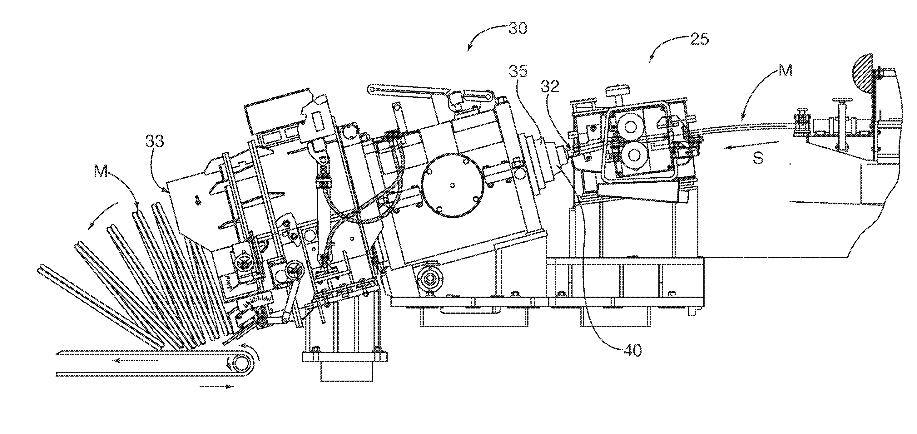
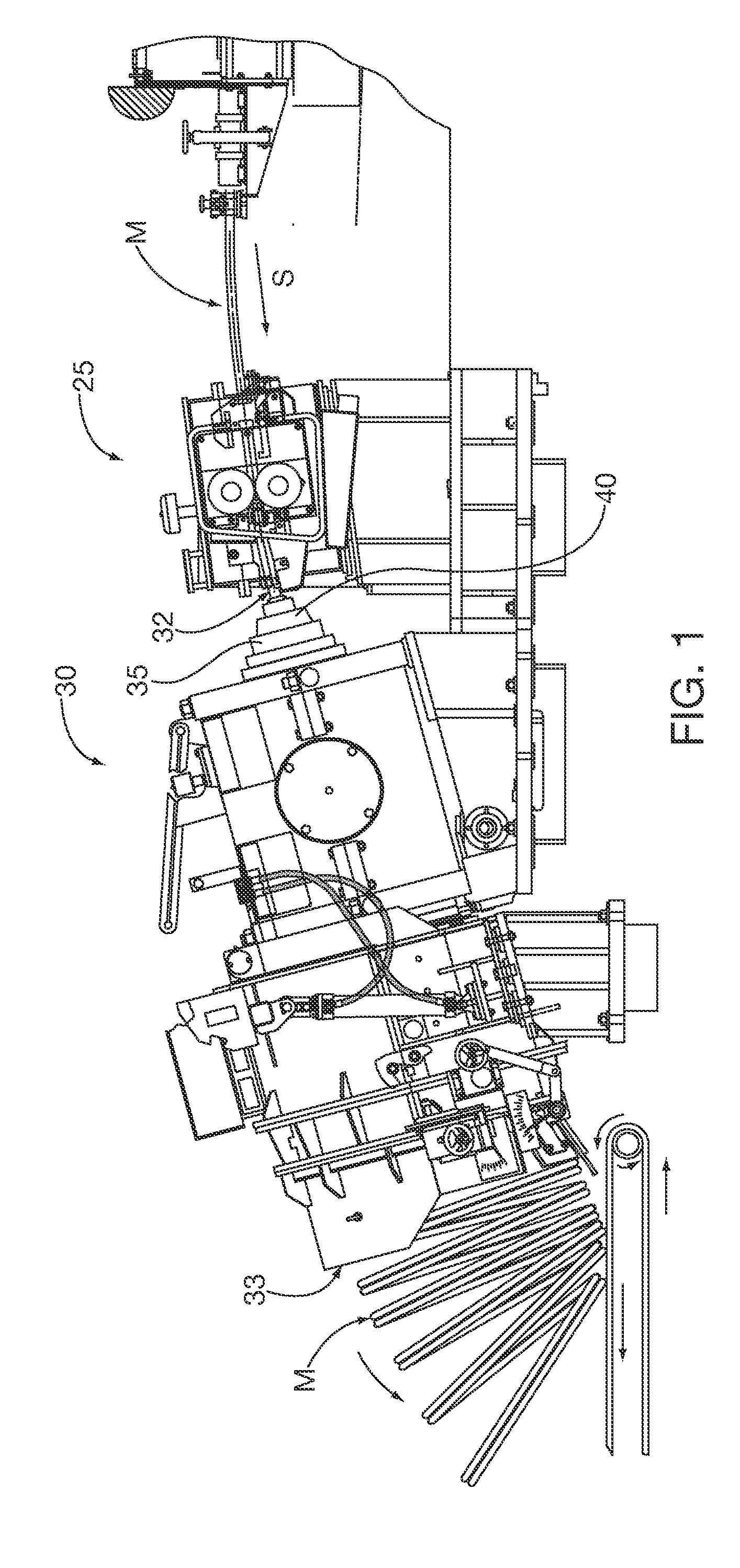
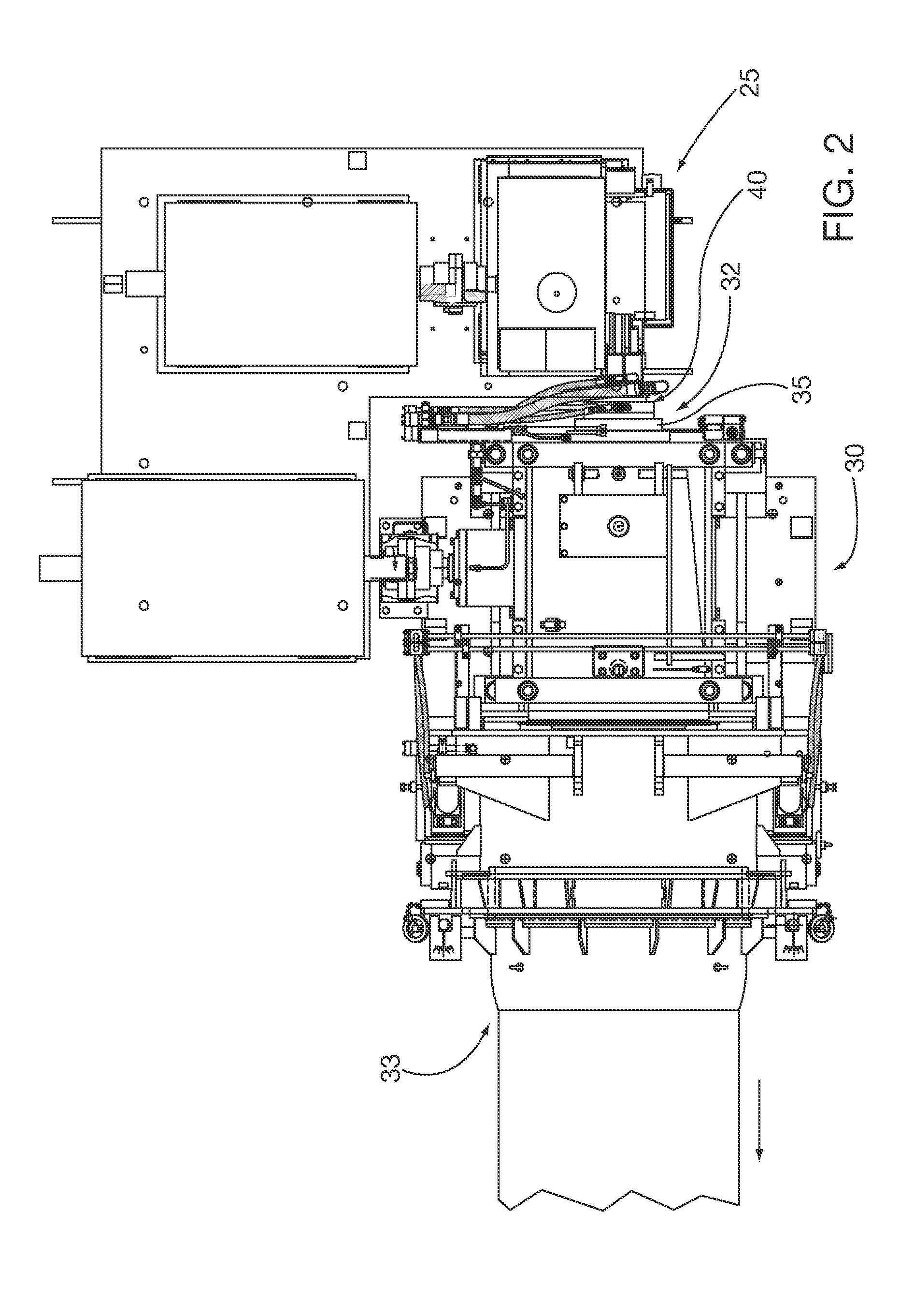
[0028]A rolling mill in accordance with an exemplary embodiment of the present invention is shown in FIGS. 1-4, and has a pinch roll assembly 25 that feeds elongated material M at a speed S into a laying head 30 proximal s...


PUM

PropertyMeasurementUnit
outer circumferenceaaaaaaaaaa
circumferenceaaaaaaaaaa
heat transferaaaaaaaaaa

Abstract

A modular coolant water jacket has a coolant tube cartridge portion and a selectively separable outer flange portion. Separation of the larger diameter outer flange portion from the cartridge portion facilitates axially oriented insertion and removal of the cartridge tube portion in radially confined spaces. Modular construction also facilitates reuse of the outer flange portion and replacement of only a worn cartridge tube portion.

Description

BACKGROUND[0001]1. Field[0002]Embodiments of the present invention relate to coolant jackets, often referred to as water jackets, for thermally isolating rolling mill equipment from hot rolled, elongated materials. More particularly, embodiments of the present invention relate to water jackets for thermally isolating bearings of rotating quills in laying heads.[0003]2. Description of the Prior Art[0004]Rolling mills shape hot elongated material that transfers heat to the operating environment. It is desirable to isolate certain roiling mill equipment, for example bearings in rotating machinery, from such heat transfer. In one type of rolling mill application laying heads coil elongated material finished product. The laying heads are fed the elongated material by upstream pinch rolls that are in close proximity to the head's proximal or receiving end. The proximal, end of the laying head often employs a gear driven, necked quill through which the hot elongated material travels within...

Claims


Application Information

Patent Timeline
Patent Type & Authority Applications(United States)
IPC IPC(8): B02C23/00B23P19/00
CPCY10T29/49817B21C47/143
Inventor TITUS, DAVID G.DAUPHINAIS, RAYMOND P.MOORE, DARYL L.
Owner PRIMETALS TECH USA
Why Eureka
Eureka Blog
Learn More