Electromagnetic coil, coreless electromechanical device, mobile body, robot, and manufacturing method for electromagnetic coil
- Summary
- Abstract
- Description
- Claims
- Application Information
AI Technical Summary
Benefits of technology
Problems solved by technology
Method used
Image

Examples
first embodiment
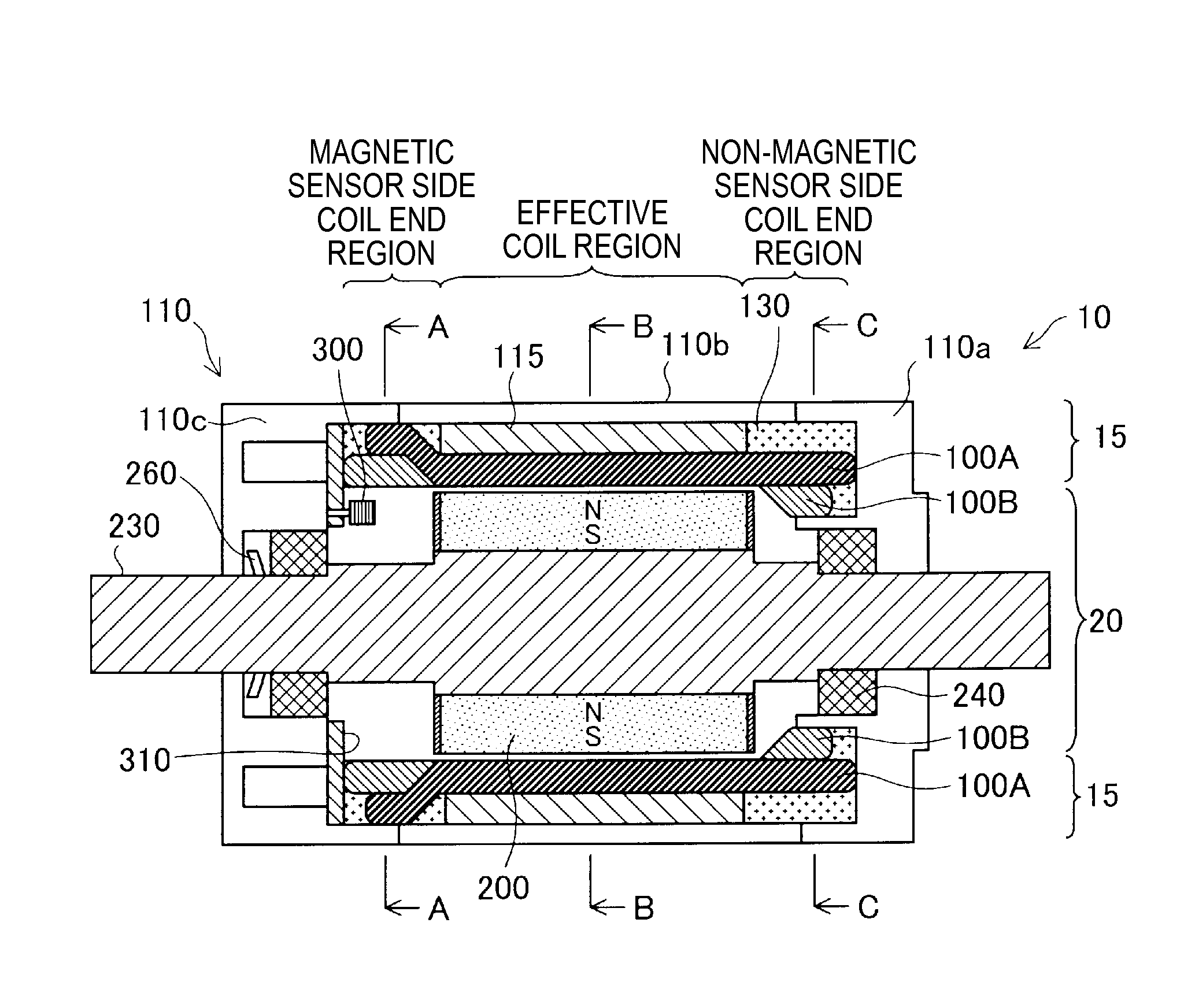
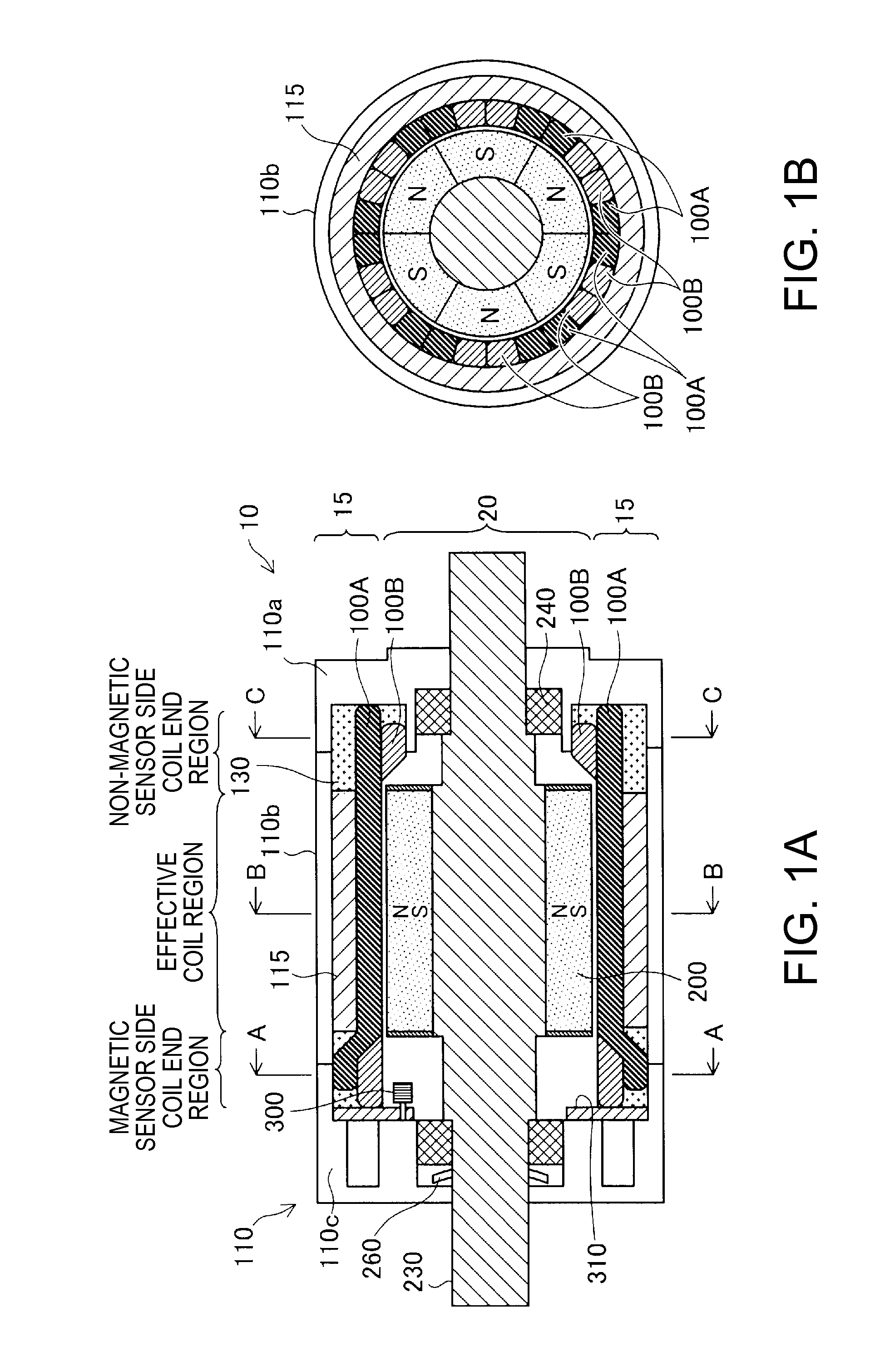
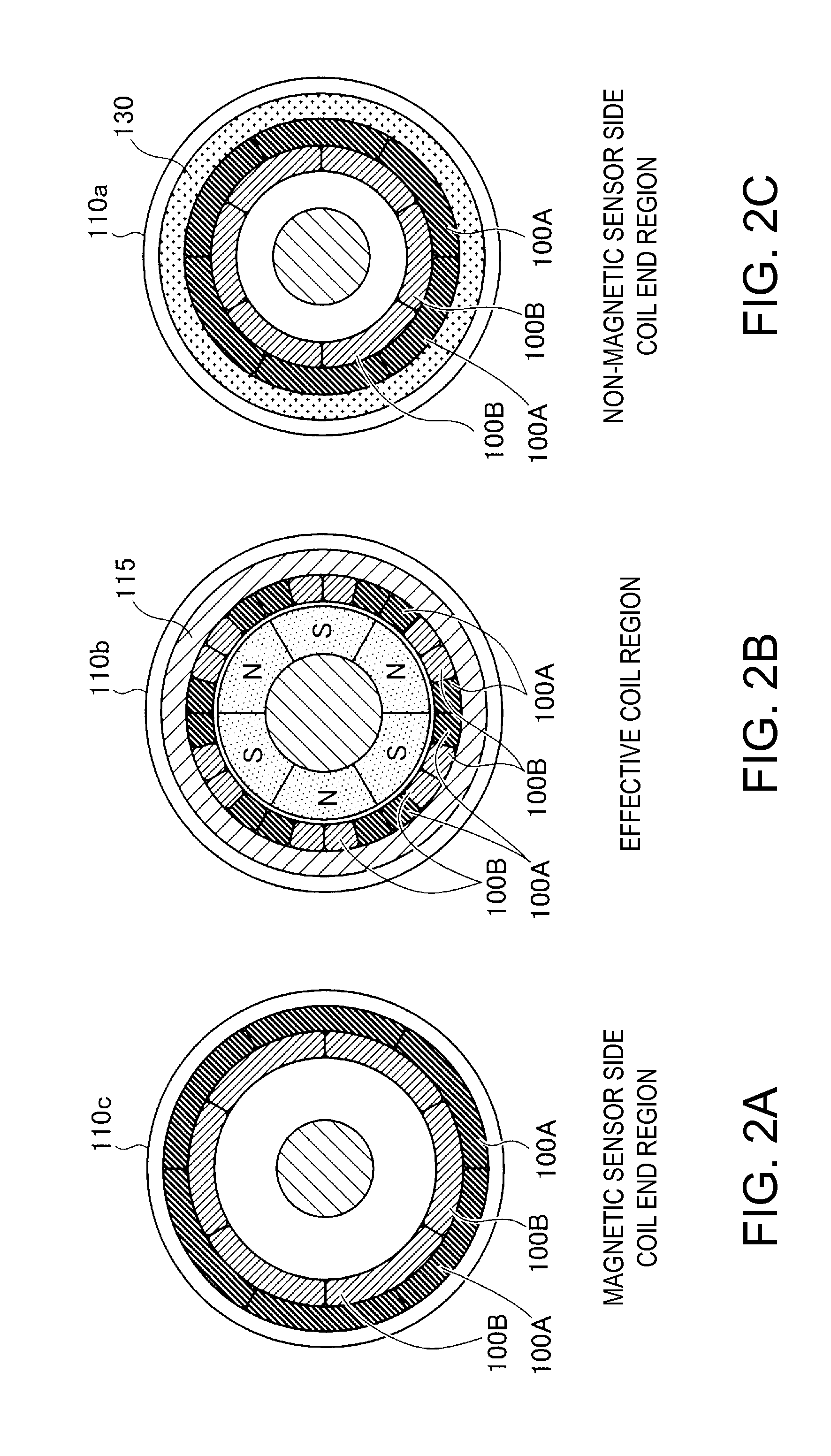
[0041]FIGS. 1A and 1B are explanatory diagrams showing a coreless motor 10 according to a first embodiment. FIG. 1A schematically shows a diagram of a schematic cross section of the coreless motor 10 taken along a surface parallel to a rotating shaft 230 and viewed from a direction perpendicular to the cross section. FIG. 1B schematically shows a diagram of a schematic cross section of the coreless motor 10 taken along a cutting line (B-B in FIG. 1A) perpendicular to the rotating shaft 230 and viewed from a direction perpendicular to the cross section.
[0042]The coreless motor 10 is an inner rotor type motor having a radial gap structure in which a substantially cylindrical stator 15 is arranged on the outer side and a substantially cylindrical rotor 20 is arranged on the inner side. The stator 15 includes a coil back yoke 115 arranged along the inner circumference of a substantially cylindrical casing portion 110b of a casing 110 and plural electromagnetic coils 100A and 100B arraye...
second embodiment
[0063]FIGS. 8A and 8B are explanatory diagrams showing a coreless motor according to a second embodiment. FIG. 8A schematically shows a diagram of a schematic cross section of a coreless motor 10C taken along a cutting line parallel to the rotating shaft 230 and viewed from a direction perpendicular to the cross section. FIG. 8B schematically shows a diagram of a schematic cross section of the coreless motor 10C taken along a cutting line (B-B in FIG. 8A) perpendicular to the rotating shaft 230 and viewed from the direction perpendicular to the cross section. The coreless motor 10C according to the second embodiment basically has the same structure as the coreless motor 10 according to the first embodiment except differences explained below. Compared with the first embodiment, in the second embodiment, as shown in FIG. 8B, the number of electromagnetic coils 100AC and 100BC is a half. According to this difference, the size of one pole of the electromagnetic coils 100AC and 100BC acc...
third embodiment
[0068]FIGS. 10A and 10B are explanatory diagrams showing a coreless motor according to a third embodiment. FIG. 10A schematically shows a diagram of a schematic cross section of a coreless motor 10D taken along a cutting line parallel to the rotating shaft 230 and viewed from a direction perpendicular to the cross section. FIG. 10B schematically shows a diagram of a schematic cross section of the coreless motor 10D taken along a cutting line (B-B in FIG. 10A) perpendicular to the rotating shaft 230 and viewed from a direction perpendicular to the cross section. The coreless motor 10D according to the third embodiment is basically the same as the coreless motor 10 according to the first embodiment except that coil end regions on both sides of an electromagnetic coil 100AD are bent from a cylindrical region where the electromagnetic coil 100AD is arranged to the outer circumferential side and coil end regions on both sides of an electromagnetic coil 100BD are not bent. A configuration...
PUM
| Property | Measurement | Unit |
|---|---|---|
| Length | aaaaa | aaaaa |
| Thickness | aaaaa | aaaaa |
Abstract
Description
Claims
Application Information
 - R&D
- Intellectual Property
- Life Sciences
- Materials
- Tech Scout
- Unparalleled Data Quality
- Higher Quality Content
- 60% Fewer Hallucinations
Browse by: Latest US Patents, China's latest patents, Technical Efficacy Thesaurus, Application Domain, Technology Topic, Popular Technical Reports.
© 2025 PatSnap. All rights reserved.Legal|Privacy policy|Modern Slavery Act Transparency Statement|Sitemap|About US| Contact US: help@patsnap.com