Load Control Device for a Light-Emitting Diode Light Source

a technology of light-emitting diodes and control devices, which is applied in the direction of electric variable regulation, process and machine control, instruments, etc., can solve the problems of power consumption of 10 w, extensive prior art dealing with led drivers, and reduced efficiency, so as to reduce increase the magnitude of the regulator voltage, and reduce the target bus voltage

Active Publication Date: 2013-03-14
LUTRON TECH CO LLC
View PDF1 Cites 187 Cited by
  • Summary
  • Abstract
  • Description
  • Claims
  • Application Information

AI Technical Summary

Benefits of technology

[0019]In addition, an LED driver for controlling the intensity of an LED light source is also described herein. The LED driver comprises a power converter circuit operable to receive a rectified AC voltage and to generate a DC bus voltage, an LED drive circuit operable to receive the bus voltage and to control the magnitude of a load current conducted through the LED light source to thus control the intensity of the LED light source, and a controller operatively coupled to the power converter circuit and the LED drive circuit. The LED drive circuit comprises a controllable-impedance circuit adapted to be coupled in series with the LED light source. The controller adjusts the magnitude of the bus voltage to a target bus voltage, so as to control the magnitude of a regulator voltage generated across the controllable-impedance circuit. The contr

Problems solved by technology

The prior art dealing with LED drivers is extensive.
It is also known that LEDs suffer from a phenomena known as “droop” in which the efficiency is reduced as the power is increased.
For example, five LEDs in a first series string each with a forward bias of approximately 3

Method used


Image

  • Load Control Device for a Light-Emitting Diode Light Source
  • Load Control Device for a Light-Emitting Diode Light Source
  • Load Control Device for a Light-Emitting Diode Light Source

Examples


Embodiment Construction

[0033]The foregoing summary, as well as the following detailed description of the preferred embodiments, is better understood when read in conjunction with the appended drawings. For the purposes of illustrating the invention, there is shown in the drawings an embodiment that is presently preferred, in which like numerals represent similar parts throughout the several views of the drawings, it being understood, however, that the invention is not limited to the specific methods and instrumentalities disclosed.

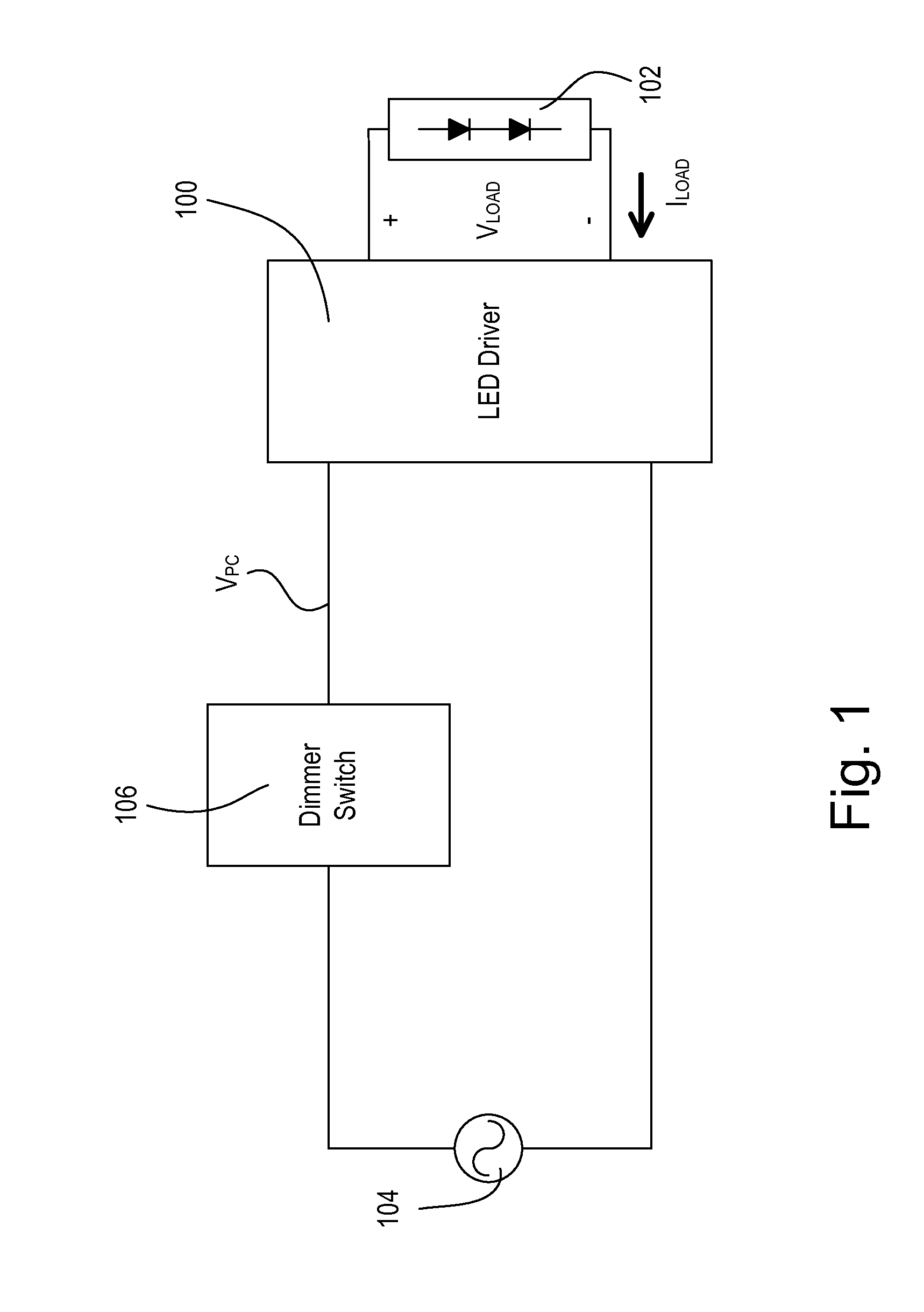
[0034]FIG. 1 is a simplified block diagram of a system including a light-emitting diode (LED) driver 100 for controlling the intensity of an LED light source 102 (e.g., an LED light engine) according to an embodiment of the present invention. The LED light source 102 is shown as a plurality of LEDs connected in series but may comprise a single LED or a plurality of LEDs connected in parallel or a suitable combination thereof, depending on the particular lighting system. In addit...


PUM


Abstract

An LED driver for controlling the intensity of an LED light source includes a power converter circuit for generating a DC bus voltage, an LED drive circuit for receiving the bus voltage and controlling a load current through, and thus the intensity of, the LED light source, and a controller operatively coupled to the power converter circuit and the LED drive circuit. The LED drive circuit comprises a controllable-impedance circuit adapted to be coupled in series with the LED light source. The controller adjusts the magnitude of the bus voltage to a target bus voltage and generates a drive signal for controlling the controllable-impedance circuit. To adjust the intensity of the LED light source, the controller controls both the magnitude of the load current and the magnitude of the regulator voltage. The controller controls the magnitude of the regulator voltage by simultaneously maintaining the magnitude of the drive signal constant and adjusting the target bus voltage.

Description

CROSS-REFERENCE TO RELATED APPLICATIONS[0001]This application is a non-provisional application of commonly-assigned U.S. Provisional Application No. 61 / 452,867, filed Mar. 15, 2011, entitled LOAD CONTROL DEVICE FOR A LIGHT-EMITTING DIODE LIGHT SOURCE, the entire disclosure of which is hereby incorporated by reference.BACKGROUND OF THE INVENTION[0002]1. Field of the Invention[0003]The present invention relates to a load control device for a light-emitting diode (LED) light source, and more particularly, to an LED driver for controlling the intensity of an LED light source.[0004]2. Description of the Related Art[0005]Light-emitting diode (LED) light sources are often used in place of or as replacements for conventional incandescent, fluorescent, or halogen lamps, and the like. LED light sources may comprise a plurality of light-emitting diodes mounted on a single structure and provided in a suitable housing. LED light sources are typically more efficient and provide longer operational...

Claims


Application Information

Patent Timeline
IPC IPC(8): H05B37/02H05B44/00
CPCH05B33/0815H05B33/0848H05B33/0824H05B45/14H05B45/44H05B45/375H05B45/385H05B45/3725H05B45/38
Inventor VESKOVIC, DRAGAN
Owner LUTRON TECH CO LLC
Why Eureka
Try Eureka