Parallel inverter drive system and the apparatus and method for suppressing circulating current in such system

a technology of parallel inverter drive and circulating current, which is applied in the direction of motor/generator/converter stopper, electronic commutator, dynamo-electric converter control, etc., can solve the problem of not revealing the operating mode of circulating current suppression, not theoretically ensuring zero-sequence current, and difficult control of the cost of the parallel inverter drive system. to achieve the effect of reducing the influence of transient performan

Active Publication Date: 2013-03-14
DELTA ELECTRONICS INC
View PDF4 Cites 35 Cited by
  • Summary
  • Abstract
  • Description
  • Claims
  • Application Information

AI Technical Summary

Benefits of technology

[0013]Another yet primary object of the invention is to provide a parallel inverter drive system and the apparatus and method for suppressing the circulating current in such s

Problems solved by technology

Nonetheless, as errors are existed among the individual inverter drives in the parallel inverter drive system, the currents of the inverter drives are not outputted to the motor in their entirety.
The error among the inverter drives that induces the circulating current may be the asynchrony of the pulse-width modulation (PWM) carrier waves, the asynchrony of the voltage commands, the system parameters, or the mismatch of the external reactors.
In this manner, the hardware arrangement of the parallel inverter drive system is constrained, and the cost of the parallel inverter drive system is hard to be controlled.
If the parallel inverter drive system is consisted of three or more inverter drives, such technique does not disclose the operating mode of achieving circulating current suppression in such parallel inverter drive system.
Nonetheless, such technique still has the f

Method used


Image

  • Parallel inverter drive system and the apparatus and method for suppressing circulating current in such system
  • Parallel inverter drive system and the apparatus and method for suppressing circulating current in such system
  • Parallel inverter drive system and the apparatus and method for suppressing circulating current in such system

Examples


Embodiment Construction

[0024]An exemplary embodiment embodying the features and advantages of the invention will be expounded in following paragraphs of descriptions. It is to be realized that the present invention is allowed to have various modification in different respects, all of which are without departing from the scope of the present invention, and the description herein and the drawings are to be taken as illustrative in nature, but not to be taken as a confinement for the invention.

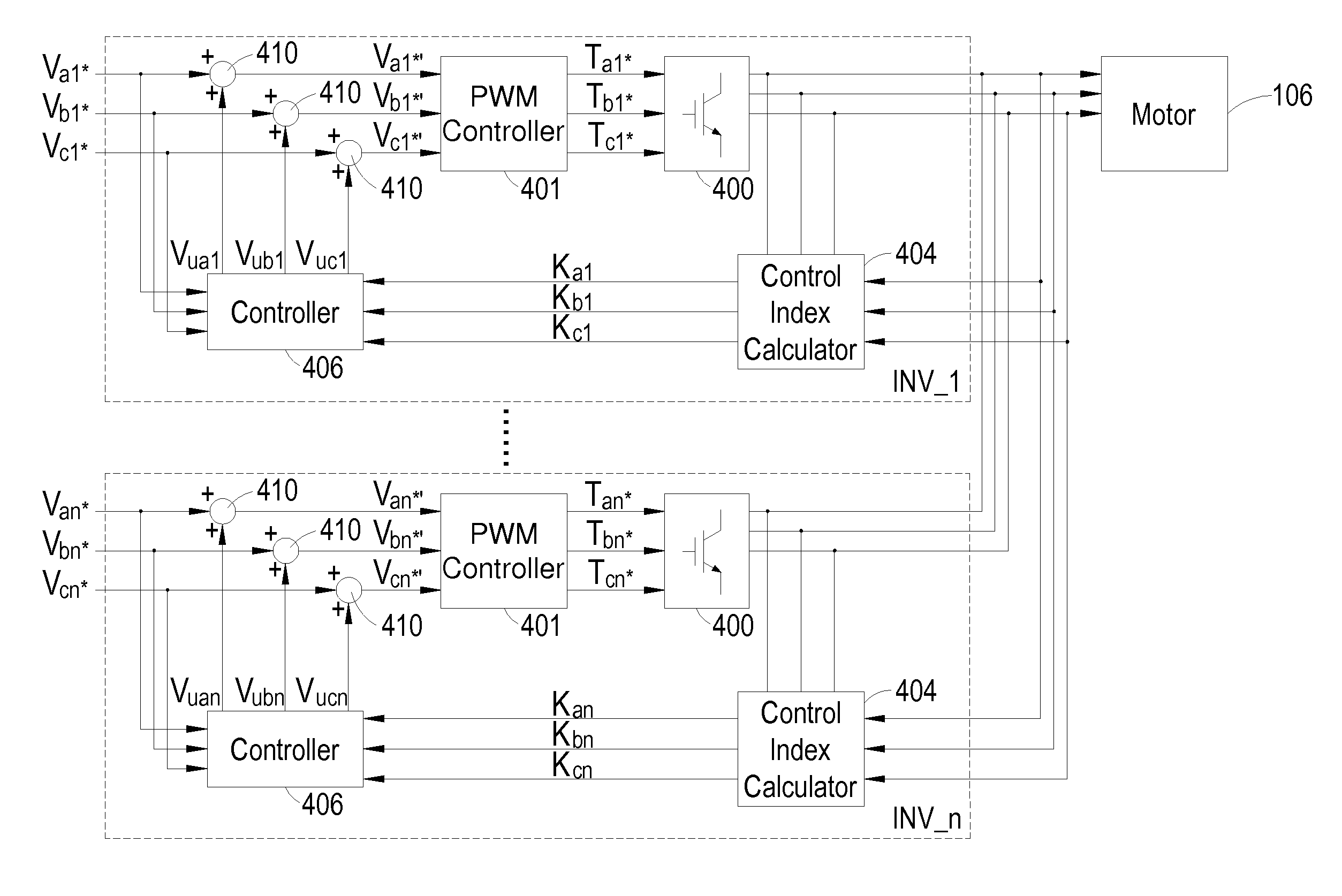
[0025]The invention proposes an apparatus and method for suppressing the circulating current in a parallel inverter drive system which is different from the circulating current suppression technique used in the prior art. Referring to FIG. 4, which is an operative block diagram of a parallel inverter drive system as well as a circulating current suppressor according to an exemplary embodiment of the invention. As shown, the parallel inverter drive system including a plurality of inverter drives INV_1, . . . , INV_n con...


PUM


Abstract

Proposed is a parallel inverter drive system including includes a plurality of inverter drives connected in parallel with each other, in which each inverter drive includes a switch; a PWM controller connected to the switch for controlling switching operations of the switch device according to a duty cycle signal; and a circulating current suppressor for collecting current information associated with the current of each inverter drive and a summation current, and generating an index according to the collected current information and the desired circulating current quantity. A zero-sequence voltage is generated for each phase of a three-phase voltage command according to the index and the voltage command and the operating mode of the inverter drive, thereby injecting the zero-sequence voltage into the voltage command with a feed-forward configuration so as to fix the voltage command. The PWM controller can generate the duty cycle signal according to the fixed voltage command.

Description

FIELD OF THE INVENTION[0001]The invention is related to a parallel inverter drive system, and more particularly to an apparatus and method for suppressing circulating currents in a parallel inverter drive system.BACKGROUND OF THE INVENTION[0002]Generally, a motor needs an inverter drive to control the rotor frequency of the motor and regulate the rotation speed of the motor, so as to drive the motor to operate. In order to increase the safety of the motor during the operation period, a parallel inverter drive system has been proposed. The parallel inverter drive system is made up of a plurality of inverter drives with their outputs being connected in parallel with each other, thereby driving the motor. The parallel inverter drive system is different from the conventional inverter drive system in that the parallel inverter drive system is made by substituting the bulky inverter drive with a number of small-volume inverter drives and allowing these small-sized volume inverter drives t...

Claims


Application Information

Patent Timeline
IPC IPC(8): H02P6/14
CPCH02P6/002H02P27/08H02P6/28
Inventor CHI, CHIEN-YUCHENG, LON-JAY
Owner DELTA ELECTRONICS INC
Why Eureka
Try Eureka